|
Title: |
1878 Article-Thomson, Sterne & Co., Hydro-Carbon Engine |
|
Source: |
International Exhibition at Paris, 1878, pgs. 138-141 |
|
Insert Date: |
2/2/2015 8:55:51 PM |
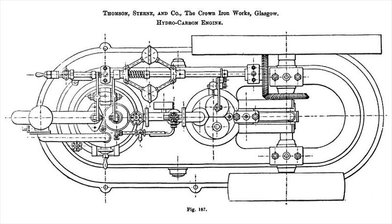
From this view, it will be seen that the bed plate of the machine consists of a very deep hollow casting of neat design, into the top table of which two vertical cylinders are recessed. The cylinder shown to the left in the engraving is the working cylinder, which is 8 in. in diameter with 12 in. stroke, while the other is the air pump, and is 8 in. in diameter with a 6 in. stroke. A pipe forms the connection between the air pump and working cylinders as shown. The air is first compressed in the air pump, whence it is delivered through this pipe past an inlet valve into the working cylinder On its way to the latter the air passes through perforated brass discs, having wire gauze placed between them, these discs being represented in the engravings just above the entrance to the working cylinder. An annular space which is shown in the section just above these discs is packed with felt, and into this packing the hydro-carbon oil is pumped from a store tank by a small pump shown on the left of the engravings, and worked by an eccentric on the shaft by which the valves are operated. From the felt the oil finds its way to the discs, over which it distributes itself. On passing through the discs the air becomes charged with hydro-carbon vapor to the extent necessary to effect its complete combustion in the working cylinder.
In the chamber just below the discs is a flame, which is caused by igniting this inflammable mixture at that point before starting the engine. This flame is constantly maintained during working, and, in one sense, may be said to have its volume increased so as to fill the cylinder at each stroke. Put in another way, each additional charge of saturated air is ignited as it passes this point, and then acts on the piston. The engine is single acting, and is fitted with a fly-wheel, the piston receiving its impulse on the down stroke. At the end of the down stroke the exhaust valve in the top of the cylinder is opened, and is closed just before the piston finishes its up stroke.
At the lower part of the engine are two malleable iron tubes, which form air reservoirs. One of these is a regulator, which is used for preventing too great variations in the air pressure, whilst the other contains a store of highly compressed air, which can be used for starting the engine instead of giving the fly-wheel a turn.
It will be noticed that the connecting rods are coupled to the working piston and air pump piston by thin plates, which permit of the necessary flexibility, there being no joints at these points. The manner in which the motion is communicated to the crank shaft through a beam mounted within the engine frame will be at once understood from the engravings. It will also be seen that the valves of the working cylinder and air pump are operated from a shaft which is coupled to the crank shaft by bevel gear and which carries the governor. It will be noticed that the opening of the valve which admits air into the working cylinder is effected by a cam on the sliding sleeve of the governor.
It is stated that in a trial with the brake this engine developed 5 horse-power, running at 200 revolutions per minute, and with 70 lb. initial pressure per square inch in the working cylinder. It will doubtless prove a very useful engine of its class for many purposes where steam is inadmissible, and where gas is not obtainable.
Price.—Engine of 5 horse-power nominal, 10 horse-power indicated, £135.
Consumption about 1 gallon of oil per hour. |
|
 1878 Thomson, Sterne & Co., Hydro-Carbon Engine
|
|