|
Title: |
1880 Article-Kendall & Gent, Boiler Shell Drilling Machine |
|
Source: |
American Machinist, 17 Jul 1880, pg. 6 & 7 |
|
Insert Date: |
7/19/2015 4:58:45 PM |
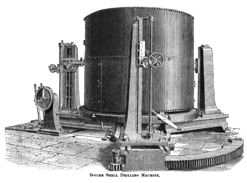
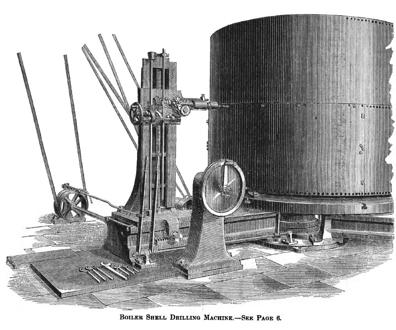
Boiler Shell Drilling Machine
On these pages are shown two views of a boiler drilling machine, originated by Kendall and Gent, Manchester, England, which we take, together with the description, from a late issue of Engineering. The probable reason why machines of this class have not been taken up by our machine builders is their large cost. If, however, they effect a considerable saving in boiler shop work they might be cheap to use, even at a large original cost.
This machine embodies a combination of the Scott patent dividing motion, as used in gear wheel moulding, with "Dixon's patent instantaneous withdrawing motion."
The dividing motion permits the pitch of the rivet holes in the circumferential seams to be regulated to any desired distance without previous "setting out" or "marking off," and the withdrawing motion brings back all the drills directly the holes are completed without any cessation of the feed motion, each drill being instantly ready for the next hole.
The machine, as constructed to drill the shells of ordinary boilers and similar circular objects, is capable of admitting boilers of 8 ft. diameter, or any smaller size down to 4 ft. diameter, and is provided with a self-acting lifting and lowering motion to the drill heads, embracing a range of 4 ft. 8 in. in height. Each head, when once adjusted to the diameter of object to be drilled, is bolted firmly down to the radial baseplate, and securely held there during the working of the machine.
The boiler shell is placed upon a revolving table actuated through patent dividing apparatus, by means of a large dividing wheel and worm placed beneath it, and the practical accuracy of this apparatus has been proved in this machine by drilling a complete circumferential row of holes in a 7 ft. diameter boiler shell and passing the drill after the completion of the last hole again to the hole it had started from, into which it freely entered without the slightest visible inaccuracy.
The feed motion to each drill is driven from one source of power, but each drill is adjustable on its own account. The depth of feed is regulated by a patent detent lever which engages with the teeth of a ratchet wheel, till released therefrom by contact with the adjustable stop. The drill spindle is then instantly forced back by the spiral spring and the forward feed motion continues.
It is the duly of the attendant to turn his dividing apparatus handle the required distance for the next hole, directly the drills are withdrawn, the amount of clearance between the drill point and the boiler shell being such as to give him proper time for this purpose but no more. Self-acting water jets to the drills, and reflectors to enable the operator to see each drill, will be provided, but were not in action at the time views of the machine were made.
With an ordinary boiler shell formed in three plates, the three drills work simultaneously, and the one movement of the dividing apparatus, of course, applies to all. If the object to be drilled be not divisible into multiples of three, any other divisions can be produced by the dividing gear, either one, two, or three drills being used, as the circumstances may permit. Two heads can be shifted round from the angle of 120 deg., at which they are shown, to positions diametrically opposite, as may be desired, and the third can be used or disused as wished.
Vertical gauge rods are provided, duly marked out to the various pitches that may be needed for the vertical rows of holes, and the movement of the drill spindle saddles is so simple and steady I hat accurate adjustment can be made without the least difficulty. In the same way when the drill would, in its natural course, come in contact with one of the bolts by which the plates are held together, the attendant can run all the drills downwards a couple of inches or so, then turn the dividing apparatus two pitches instead of one, and on raising the three drills again he can continue the circular row as before. The entire control of the machine is governed by the attention of one man to two levers and the one dividing handle, which are all conveniently placed for the purpose. |
|
 1880 Kendall & Gent, Boiler Shell Drilling Machine
 1880 Kendall & Gent, Boiler Shell Drilling Machine
|
|