|
Title: |
1880 Article-Morse Twist Drill & Machine Co., Automatic Twist Drill Grinding Machine |
|
Source: |
American Machinist, 31 Jul 1880, pg. 5 |
|
Insert Date: |
7/20/2015 8:01:48 PM |
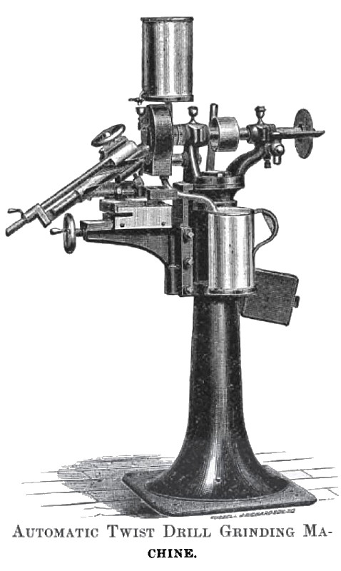
New Twist Drill Grinding Machine
An engraving herewith represents a new automatic twist drill grinding machine just brought out. The machine is mounted on a pedestal as shown in the cut. The table is movable on the vertical slide by means of a lever. It is balanced by a counterweight, as shown on the right. Moving the table presents the drill to different parts of the cutting face of the wheel, and by a little care the wheel can be kept true without the use of a diamond. The wheel has a bonnet carrying a water receptacle, and conductor which distributes the water to the face of the wheel. The waste water is carried off by a drip pipe to the can shown in the cut. The bonnet is so arranged that it can be moved back as the wheel wears.
The drill is held by a chuck or holder. The jaws in this chuck are self-centering and are moved by a right and left hand screw actuated by a hand-wheel. The chuck is pivoted to a standard at the back (not shown in the cut) so that it can be revolved in a vertical plane. The base of the standard is pivoted to the carriage so that, it can be revolved in a horizontal plane by the handle shown at the extreme left of the cut. These revolutions give the clearance which can be regulated as follows: A cross-slide, not very distinctly shown in the cut, has links connected with it. When the slide is so placed that this connection is concentric with the center of revolution of the standard, the links do not act, and the amount of clearance is governed by the distance between the center of revolution and the face of the wheel. If the slide should be moved to the right, the connection is made eccentric with the center of revolution. The shank of the drill is raised as the standard revolves, thereby crowding the heel of the drill harder on the wheel and giving more clearance.
The carriage moves to and from the pedestal on the slide, as shown, motion being given by the hand-wheel, shown at lower left hand side. Motion can be limited by check nut on the side opposite the observer.
The small wheel on the right is intended to be used in thinning the points of the drill, which become thicker as they approach the shank.
To grind a drill the handle is placed at the extreme left. The drill is then clamped between the jaws with one cutting lip vertical bearing against, and extending a little beyond, a guide not shown in the cut. Drills from ½" to 1½" in diameter should project beyond this guide enough to secure the necessary stock for grinding without cutting the guide; larger drills should project from ¼" to½". The stop, near tip of handle, is then moved up against the shank of the drill and fastened. The machine being started, the carriage is moved forward until the wheel begins to cut. The handle is then swung to the right until the face of the drill is clear of the wheel. It is then swung to the left again, until the swinging base bears against the stop, and the operation repeated; the carriage being moved forward as fast as the stock is removed, until a perfect cutting edge is obtained. The check nut is then placed against the carriage and the carriage run back. With the handle at the extreme left, loosen the jaws of the chuck and turn the drill half round, or until the second cutting lip is in the same position as the first was, which is determined by the guides. The second lip is then ground in the same way as the first lip until the carriage is stopped by the check-nut. The lips are now of the same length and have the same angle with the axis of the drill.
In the above operation the cross-slide has been at the zero mark. This position will in most cases give sufficient clearance. If for any reason more clearance is desired, it can be obtained as follows: With the handle at the extreme left, move the slide to the right. This will change the angle of the cutting lip, which must be readjusted. One of the series of links is an extension link and this is now lengthened until the mark on the chuck holding the drill coincides with the mark on the standard. When the handle is swung to the right, the shank of the drill is raised and the heel of the drill pushed forward, thereby securing more clearance.
The spindle is of steel and provided with improved bearings, so designed as to secure a firm and steady motion to the wheel in operation. The machine, which is well built, is arranged for drills ½ to 2 inches diameter. With extra jaws, drills to ¼ inch diameter can be ground.
The machine is manufactured by The Morse Twist Drill & Machine Co., New Bedford, Mass. |
|
 1880 Morse Twist Drill & Machine Co., Automatic Twist Drill Grinding Machine
|
|