|
Title: |
1920 Article-Hanson-Whitney Machine Co., Oil Grooving Attachment |
|
Source: |
Machinery, V27, Oct 1920, pgs. 181 & 182 |
|
Insert Date: |
11/9/2015 7:58:00 PM |
HANSON-WHITNEY OIL-GROOVING ATTACHMENT
Probably it is safe to say that the oiling of slides in 1achinery has never received the same careful consideration that has been given to the oiling of revolving bearings, but accuracy and freedom from wear in a slide is just as important as in any other bearing of a machine. Oil-grooves are provided to distribute lubricant over a slide bearing. and when these grooves are chipped, the operation is expensive and the quality of workmanship is difficult to control. Many machine designers leave the question of making oil-grooves to the judgment of men in the machine shop; whereas, the form of grooves to be used should be definitely specified and standard tools should be available for their production. Many experienced machine designers prefer a V-shaped groove of about 120 degrees included angle to an oil-groove of half-round section, because it helps the oil to 'wedge itself between the wearing surfaces. Also, the oil-groove should be of the so-called zigzag form, as shown in the accompanying illustrations. The V-shaped groove has a further advantage in that it is possible to produce different widths of grooves with the same tool.
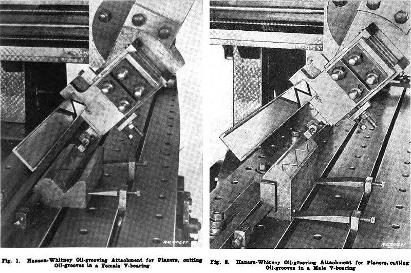
To provide for the rapid and accurate cutting of oil-grooves in slides, the Hanson-Whitney Machine Co., Hartford, Conn., has developed a planer attachment which is here illustrated and described. This device can be used on any standard type of planer and it is furnished with a master cam which guides the oil-grooving tool to provide for producing a groove of accurate form. It is said to take practically no longer to set this tool up on a planer than it does other tools that are used on the machine; and attention is called to the desirability of cutting oil-grooves while a piece of work is on the planer, instead of making this an entirely separate operation.
Features of the Oil-Grooving Attachment
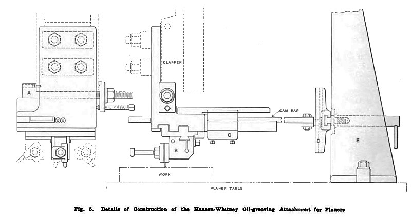
This attachment is secured in place on the machine by means of the clapper bolts, and the holes are not drilled for this purpose, owing to the fact that the location of the bolts varies on different machines. In setting up the attachment, it should be located on the clapper so that the hook-bolt A, Fig. 5, touches the bottom of the clapper. When the hook-bolt is tightened, the clapper will be squeezed so that it cannot move. In the hook-bolt there is a hole into which a hardened bushing is driven; and a drill that fits this bushing should be used to drill a hole into the clapper-box. A pin which fits the hole in the hook-bolt should then be driven into the clapper-box, and this pin and the friction of the clapper squeezed between the fit of the box will hold the attachment firmly in place; but the bolts in the clapper-box should also be tightened up.
On the oil-grooving attachment there is a small clapper-box B, which can be adjusted along a reciprocating slide; and various widths of zigzag paths for the oil-grooves can be obtained by adjusting the clapper G which transmits movement from the cam bar to the reciprocating slide. The cam bar is attached to cross-piece D, which is connected to upright E, this upright being strapped to the planer table at a convenient position, while the cross-piece is located at approximately the correct height on the upright. The cam bar can slide vertically in the cross-piece, and the cross-piece slides horizontally on the upright, thus affording considerable freedom of action for the grooving attachment in both horizontal and vertical directions.
Forms of Oil-grooving Tools
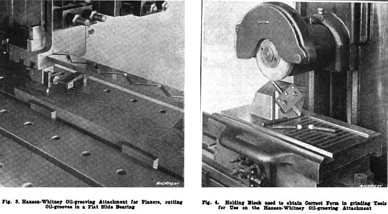
Three forms of oil-groove cutting tools are used. For work where there is no projection, a straight tool is used and it is always located at right angles with the surface to be grooved. When an oil-groove has to be made in a dovetail, either a right or a left-hand tool is employed according to the form of the work, and the tool should always swing at 45 degrees to give the required cutting angle. When cutting oil-grooves in V-shaped slides, such as those in a planer bed or on the V-part of a large planer table, the whole oil-grooving attachment is swung by adjusting the clapper-box or the vertical slide, or by a combination of these two movements. When planing grooves in a 45-degree angle V-bearing, it is found most satisfactory to swing the clapper-box to 20 degrees and the vertical slide to 25 degrees. On this oil-groove cutting attachment the maximum length of groove that can be cut is 30 inches; the maximum width of the zigzag path for the oil-groove is 1¼ inches, and the minimum width of the zigzag path is 3/8 inch.
Method of Procedure in Sharpening Tools
To provide for rapidly and accurately sharpening the cutting tools used on this planer attachment, a special holding block is furnished. Any grinder, such as the Brown & Sharpe surface grinder, or the Cincinnati cutter grinder, will give satisfactory results for this purpose. From Fig. 4 it will be apparent that the block is provided with grooves in which the cutting tool is strapped, so that the combination of the angularity of the groove and the supporting face of the block will provide for bringing the tool into contact with the grinding wheel in such a position that the desired form of tool point will be secured. |
|
 1920 Hanson-Whitney Machine Co., Oil Grooving Attachment, Figs. 1 & 2
 1920 Hanson-Whitney Machine Co., Oil Grooving Attachment, Figs. 3 & 4
 1920 Hanson-Whitney Machine Co., Oil Grooving Attachment, Fig. 5
|
|