|
Title: |
1876 Article-Robey & Co. Ltd., Steam Tracion Engine |
|
Source: |
Scientific American Supplement, V1-2, 05 Feb 1876, pg. 85 |
|
Insert Date: |
11/20/2015 7:30:21 PM |
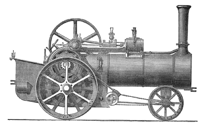
The reward of ten thousand dollars offered by the State of Wisconsin (published in Scientific American, January 29th, 1876), for the best form of road locomotive, lends a special present interest to the subject, and we therefore reproduce from Engineering one of the latest and best examples of British practice in road locomotives. This is a 6-horse power engine, by Messrs. Robey & Co., of Lincoln. Messrs. Robey, to relieve the boiler of the strains due to the working of the engine, have interposed between the cylinder and the crankshaft a cast-iron bedplate, one end of this bed forming the cylinder cover, while the other carries the crankshaft plummer blocks. In the case of their portable engine, where the cylinder is over the firebox end of the boiler, the crosshead guides and the exhaust-pipe are cast solid with the bedplate, while the latter takes a sliding bearing at the crankshaft end upon two brackets fixed one on each side of the boiler, one of these brackets having the pump made in one piece with it. In the case of the traction-engine the bedplate has the crosshead guides cast solid with it, while, as in the case of the portable, the bed from its shape forms a receiver for any oil dripping from the moving parts.
In the traction-engine the expansion of the boiler is accommodated by leaving the crankshaft end of the bedplate free to move between the horn-plates, it being held to them by a plate on each side. These plates are made fast to the bedplate, and slide horizontally in slots cut in the horn-plates. The horn-plates reach the whole depth of the firebox, and are deeply flanged outwards, on both sides, for strength, and for attachment to the boiler and water tank. The second motion shaft is carried in a U-shaped casting let into the horn-plates, and stretching between them, acting thus as a stay and distance piece. The main axle is also carried by the horn-plates, which also form the sides of a part of the water-tank. The usual arrangement of steerage gear is modified, the chains being attached to the extreme ends of the axle, by means of grooved castings, so curved as to keep the chains tight in all positions, and facilitate steering. The leading wheels, it will be noticed, are set to a narrower gauge than the driving wheels. The engine is very completely equipped, having water-lifter (injector type) for filling the tank from roadside ditch, etc.
The driving wheels have the arms arranged in two sets, each set of arms being welded to a plate at the centre, which is bored out and fitted with the boss, the rivets holding it up, thus having no shearing strain on them. By the arrangement of the arms in sets, if one arm gets broken the whole set can be removed and a new arm welded on, which is impossible if the arms are cast in the boss.
The engine is fitted with two speeds, and the arrangement of the clutches is shown by the detail views. It is also provided with a neat form of high-speed governor for use when the engine is employed for thrashing, etc. |
|
 1876 Robey & Co. Ltd., Steam Tracion Engine
|
|