|
Title: |
1922 Article Universal Boring Machiine Co., Horizontal Boring Machine |
|
Source: |
Machinery Magazine, V28, Jan 1922, pg. 413 |
|
Insert Date: |
1/30/2016 12:14:02 PM |
UNIVERSAL "TRI-WAY" HORIZONTAL BORING MACHINE
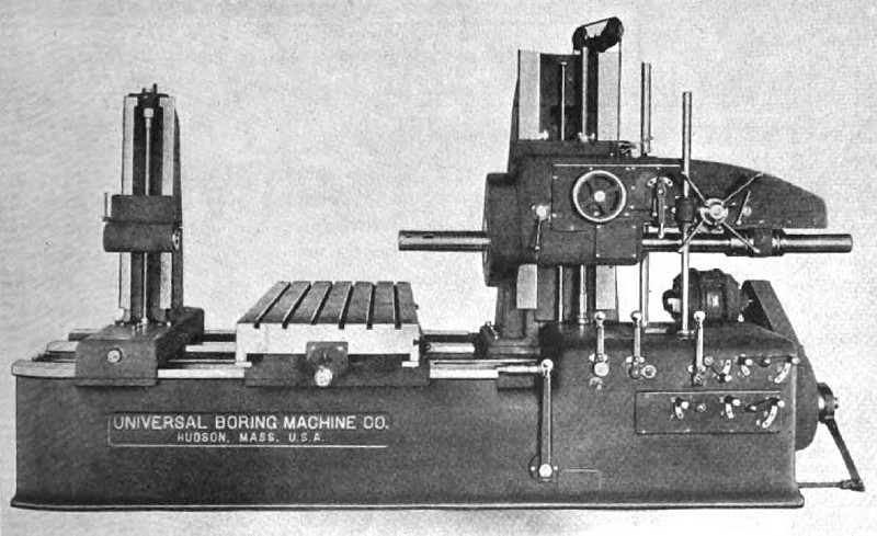
A newly designed horizontal boring machine intended for handling heavy work in railroad and other shops, which is known as the "Original Tri-way" from the fact that the bed has three flat ways, has been placed on the market by the Universal Boring Machine Co., Hudson, Mass. The front one of the three ways and the center way serve as guiding surfaces for the sliding members on the bed, while the rear way helps to support the long carriage. The construction will be apparent by reference to Fig. 1. The bed is also designed for a coolant system, the top sloping toward the head end so that the coolant runs into a settling chamber at the end of the bed. From this settling chamber it overflows into another chamber from which it is pumped through piping to the work.
The design of the carriage and table is similar to that of the No. 3-A and 3½ machines built by this concern, except that the members are heavier and are designed to take care of coolant without piping. The head post has been provided with wide bearing surfaces for the head. The head has a reversing lever for the boring-bar, slow hand-feed for the boring-bar, and a lever for throwing in the higher boring bar speeds. The hand-wheel on the head is used to obtain the fine hand-feeds, and the sprocket wheel for rapid hand-feeds. The vertical lever between the two is for reversing.
The starting and stopping lever of the machine is at the front of the bed and operates a friction clutch that controls the rotation of the main driving shaft. The gears for obtaining the various speeds and feeds are arranged in geometrical progression, and are operated by levers at the right-hand end of the bed. Attention is called to the convenient location of all control levers at this end of the machine. The left-hand upright lever is employed for throwing in either the table cross-feed, the longitudinal carriage feed, or the vertical head feed. The central upright lever is used to throw in all feeds and to effect rapid traverses, while the right-hand upright lever is used to reverse the feeding of the various members.
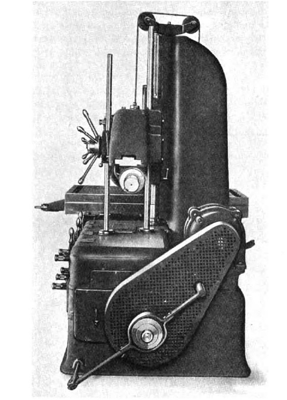
Wear of the rear post elevating screw may be compensated for by means of the nuts at the upper end of the screw. Prom the end view of the machine shown in Fig. 2, the method of mounting the driving motor may be readily observed. A few of the principal dimensions of the machine are as follows: Automatic travel of main boring-bar, 30 inches; travel of main boring-bar by resetting, 60 inches; size of table, 30 by 63 inches; power cross-feed of table, 48 inches; power longitudinal feed of carriage, 40 inches; power vertical feed of head, 30 inches; maximum distance from table to center of boring-bar, 30 inches; and greatest distance from faceplate to outer support, 72 inches. |
|
 1922 Universal Boring Machiine Co., Horizontal Boring Machine
 1922 Universal Boring Machiine Co., Horizontal Boring Machine (End View)
|
|