|
Title: |
1921 Article-G. A. Gray Co., Iron Planer (Rail Locking Mechanism) |
|
Source: |
Machinery, V28, Dec 1921, pg. 286 |
|
Insert Date: |
6/18/2016 9:29:50 PM |
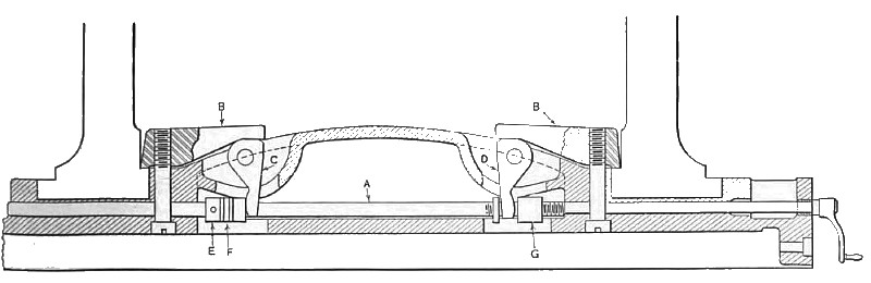
The rail is clamped by means of the device illustrated in Fig. 5 in which two steel clamps B are fastened to the rail by heavy screws. These clamps engage ledges on the inner edge of the housing faces and are capable of slight rotation due to play of the screws in the rail. Bell-crank levers C and D bear against the inner end of the clamps, and are secured to the rail by pins. A collar E is pinned on shaft A, and interposed between this collar and the projecting end of lever C is a ball thrust bearing F. The longer end of bell-crank lever D engages a nut G on shaft A. The latter is parallel with the rail screws and projects from the operator's end of the rail, where it has a squared end similar to the rail screws. When it is desired to unclamp the rail, it is only necessary to remove the crank handle from one of the rail screws, place it on the end of the rail lock-shaft and give this shaft three turns. This causes nut G and collar E to separate, which results in rotating levers C and D about their pins and moving clamps B away from their ledges. Turning the handle in the opposite direction with a moderate effort draws the longer ends of O and D together, and clamps the rail securely to the housing.
The two clamps B bear on the ledges with exactly equal force, since the same pull is exerted upon each of the levers C and D; this prevents slippage of one side of the rail and resulting inaccuracy of the work. Moreover, it is impossible with this device to neglect to clamp or unclamp one side of the rail. By clamping the rail at the inside, the length subject to torsion is reduced, and the increased power of the clamp makes it unnecessary to use four clamps to hold the rail.
The rail-elevating mechanism is operated by a lever placed on the right-hand side of the machine. From this lever, a stirrup is suspended by a universal joint, as can be clearly seen in the heading illustration. The lever is normally locked in position, but a quarter turn of the wrist unlocks it, permitting it to be pushed up or pulled down. Moving the lever, clutches the elevating shaft to the reduction gears previously referred to, and simultaneously starts the motor. The operator, when holding the stirrup, stands in front of the housings where he can plainly see both the rail and the work. If the operator wishes to raise or lower the rail, he has only to turn the rail-locking shaft three turns to the left, push up or pull down on the stirrup, and then turn the rail-locking shaft again three turns to the right. |
|
 1921 G. A. Gray Co., Iron Planer (Rail Locking Mechanism)
|
|