|
Title: |
1921 Article-G. A. Gray Co., Iron Planer (Lubricating Pump) |
|
Source: |
Machinery, V28, Dec 1921, pg. 287 |
|
Insert Date: |
6/18/2016 9:33:43 PM |
Provision for Lubrication
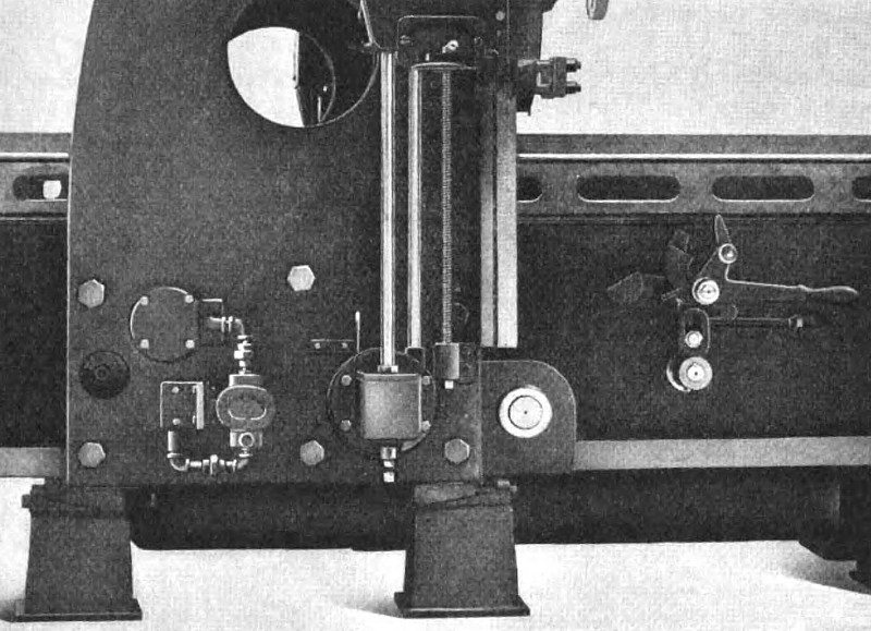
The accuracy and durability of a machine tool depend greatly upon the system of lubrication provided. If an oil film is always maintained between bearing surfaces, the surfaces are subjected to less wear and the machine will maintain its accuracy longer. The Gray planer is provided with a system of forced lubrication, a Brown & Sharpe geared pump being bolted to the left-hand housing and driven from the pulley shaft by means of a flexible coupling. The pump takes its supply of oil from a large cast-iron reservoir bolted to the bottom of the bed, and discharges through a filter in the housing. The filtering material can be readily removed and replaced by taking off the hand-hole cover shown in Fig. 6. Piping leading from the filter passes to the various bearings so that they are abundantly supplied with filtered oil, the used oil draining back into the reservoir from which it is pumped.
The oil supply is maintained at the proper pressure by a combination pressure relief valve and an accumulator placed in the line. Piping from the filter also leads to two holes drilled into the vees of the bed at the center of its length. Each table vee has a large oil-channel from which the numerous supplementary oil-grooves carry oil to all parts of the bearing surfaces. These oil-channels run the length of each table vee, and are closed at the ends. By this means the oil pressure is maintained constant throughout the entire length of the table. This design has the advantage that the oil supply is equal at all points, no matter what the relative position of the table and the oil supply in the bed may be. If short stroke work is being done near one end of the table, for instance, the oil does not have to flow through a long groove of limited area to reach the far end of the table. The surplus oil dripping from the vees and table rack flows through a heavy screen into a settling basin at each end of the bed and returns to the central reservoir through piping contained in the bed. In order to support the table when it is in its extreme position and to prevent the dripping of oil from the vees to the floor, the bed is made twice the length of the table. This prevents the table from springing, as there is no overhanging weight, and thus prevents the end of the bed from cutting the underside of the table. It also makes unnecessary special projections for catching the dripping oil, and constitutes a safety feature, since the table never extends beyond the bed |
|
 1921 G. A. Gray Co., Iron Planer (Lubricating Pump)
|
|