|
Title: |
1921 Article-Clark-Mesker Co., #2 Cleveland Horizontal Milling Machine (Part 1) |
|
Source: |
Machinery, V28, Jan 1922, pgs. 373-376 |
|
Insert Date: |
6/22/2016 5:16:50 PM |
The efforts to produce machines to meet, in the best way possible, the demands for adaptability to a large variety of work, ease of operation, rapidity and accuracy of production, and length of service, have been largely responsible for the evolution of standard machine tools to the present-day designs. By these constant efforts the milling machine has advanced to its present stage of development. The heading illustration shows a modern machine of this type—the Cleveland milling machine built by the Clark-Mesker Co., Cleveland, Ohio. A patent covering the distinctive features of this machine has just been issued and, in view of this, it is believed that a description of the design will prove of interest to those engaged in machine tool design and to users of machine tools.
Construction of the Column and Over-Arm
The column and base of the machine consist of a one-piece semi-steel casting adequately ribbed to give a rigid construction. As shown in Fig. 1, the lower portion of the column on the inside is formed into a chamber in which is kept a supply of coolant for the cutters, the coolant being conveyed to the cutters through the medium of the centrifugal pump B which is driven from the main driving shaft A through bevel gears and a vertical shaft. By driving the pump directly from the main shaft the supply of coolant to the cutters is automatically cut off when the machine is stopped. The bracket for the pump and its driving shaft is suspended from a rib which separates the coolant chamber from the compartment occupied by the main driving shaft and the speed-change gearing. A gasket is placed between the flange of the pump bracket and the rib so as to prevent oil leaking from the upper compartment into the coolant chamber. The pump forces the coolant to the cutters through piping which may be seen in Fig. 3, the coolant being later returned from the table to the chamber through a hose. The coolant chamber is filled through an opening in the right-hand side of the column which is provided with a suitable cover.
A feature of the machine is the square over-arm, the main advantage claimed for this design being that it provides a positive alignment of the arbor supports and the arbor with the other machine members. The over-arm is held snugly in the column by a cap having 90-degree V-grooves which mate with similar grooves in the column proper. The cap is aligned on the column through the use of a taper gib and dowel-pins, and the over-arm is clamped in place by binding members C, Fig. 1, each of which has two cylindrical parts connected by a screw that projects from the left-hand side of the column. These cylinders have beveled surfaces on the ends in contact with the square over-arm, and clamp the latter when the bearing surfaces are drawn against it by rotating the binding screw. The two arbor supports are clamped to the over-arm in a similar manner.
Lubricant for the various gears in the upper compartment of the column is supplied through opening D. The compartment should be filled to a level midway across a gage glass on the left-hand side of the column, which may be seen in the heading illustration below the main driving shaft. To fill to this level requires approximately five gallons of oil, but it is only necessary to do this about twice a year. A fine mist of oil is created in this compartment when the machine is running, due to the revolution of the gears.
The Spindle Driving Arrangement
Power to the cutter-spindle, the knee-elevating mechanism and the table feeds is transmitted through shaft A, Fig. 1, from the constant-speed pulley E which drives shaft A by means of friction clutch F. The pulley is mounted on the hub of the clutch-driving member, and this entire unit is supported by a bracket bolted to the rear of the column. Clutch F is controlled by levers A, Fig. 3, on each side of the column, located close to the table. The drive from the main shaft to spindle G, Fig. 1, is through a set of change-gears which ends in two gears keyed to the spindle. This arrangement furnishes sixteen speeds in geometrical progression, in either direction.
Power is transmitted from the driving shaft to the first gear H in the speed-change train, either direct through clutch L or through three bevel gears, I, J, and K and clutch L. The clutch is keyed to shaft A, and when it is brought in mesh with the sleeve on which gear H is mounted, the latter is driven in a direction opposite to that in which it revolves when the drive is through the bevel gears previously mentioned. Clutch L is operated by a lever on the left-hand side of the column, which may be seen in the heading illustration adjacent to the oil-gage. With this arrangement only one speed, in either direction, can be transmitted to shaft M, Fig. 1, this being accomplished by means of the gear at the rear end of shaft M which meshes with gear H.
Two sliding gears U and V on shaft M and four gears which are held stationary axially on a sleeve N that revolves on a shaft enable any one of four speeds to be transmitted to the sleeve. From this sleeve power is transmitted to shaft O through two pairs of sliding gears W and X. which mesh with gears keyed to sleeve N. Sliding gears W and X have clutch teeth on both ends, and when gear W is pushed to the rear, the clutch teeth on this end engage similar teeth on gear Q, thus driving this gear directly. When the sliding gear is brought to the front its teeth engage those of clutch P so that gear Q is driven through the clutch and the sleeve on which the clutch and gears are mounted. Similarly sliding gear X drives gear R either through the clutch teeth mounted adjacent to this gear or through clutch P. Gears Q and R mesh with gears keyed to the spindle, and as gear Q is mounted on a sleeve, and gear R really consists of a sleeve with teeth cut on one end, when either of these gears is transmitting the drive, the other rotates idly on shaft O. The sliding gears on shafts M and O are operated by ball-joint lever A, Fig. 4, located on the left-hand side of the column. The forks operating the sliding gears are made interlocking so as to prevent the engagement of both pairs of gears at one time.
Adjustment of the Spindle
The spindle is flanged at the front end, and the face of this flange has a keyway into which may be inserted hardened steel laws for driving arbors and face mills. Wear on the front and rear spindle bearings may be compensated for by adjusting nut S (Fig. 1) at the rear end of the spindle. The spindle may be hand-operated by turning wheel T, which is a convenient feature when boring jobs and some milling operations are being performed. Positive locking of the spindle is effected through a small crank-lever on the left-hand side of the column near the rear, which may be seen in the heading illustration. This locking device cannot be operated while the machine is running and neither can the main driving clutch F. Fig. 1, be brought into contact with its driving member when the spindle is locked. The positive locking feature enables the operator to remove arbor nuts without difficulty. The drew-in bolt Y provided for holding arbors or cutters in the socket end of the spindle may be rotated by applying s crank-handle on the rear squared end.
The Knee-elevating mechanism
Reference to Fig. 2 will show that the gearing for elevating or lowering the knee and feeding the saddle and table is all contained in the knee, the latter consisting of a main casting gibbed to a dovetail slide on the column and a casing A in which the major portion of the gearing is contained. This construction enables ready unit assembly and facilitates lubrication of the transmission members as a sufficient quantity of oil can always be kept in casing A for some of the feed-gears to dip into power is transmitted to the knee-elevating and table feeding mechanisms from shaft A. Fig. 1, through bevel gears a and b, and spur gears c and d, gear d driving the extremely wide faced spur gear B, Fig. 2. The extreme width of gear B is necessary on account of the vertical movement of the knee. Gear C also meshes with gear B and transmits power to shaft D through bevel gears, the drive being connected and disconnected by operating clutch E, which is controlled by a lever on the left-hand side of the knee. When clutch E is in engagement with bevel gear F, the rotation of shaft D is in the opposite direction to that in which it revolves when the clutch is in engagement with gear G. This arrangement enables the knee to be elevated or lowered, the saddle fed to the front or rear, and the table to the right or left.
From shaft D power for operating the knee mechanism is transmitted to sleeve gear H through trains of feed-change gears which are connected by either of sliding gears I or J and which drive gear K mounted on a sleeve on shaft L. Power from gear K is transmitted to gear H by engaging the teeth of clutch M with those of the clutch member mounted on shaft L, adjacent to gear K. Gear H drives its mating bevel gear V on the top of the elevating screw N. The threads of this screw engage those of nut O which is held in a post mounted on the base and is automatically lubricated. The knee is raised or lowered according to the direction in which the screw is rotated. The main knee casting has a bearing on the post in which the screw nut is mounted. Gear V has teeth on the upper side as well as on the lower, the upper teeth meshing with a pinion that may be rotated by hand by turning crank B, Fig. 3, when the power feed is disengaged.
Saddle and Table Feeds
Sixteen feeds to the saddle and table in geometrical progression are provided through the change-gearing in the knee; these are obtained by operating handles on the front of the knee as shown at C in Fig. 3. The saddle is adjustable on a dovetail slide on the knee, and is fed across the knee by means of a screw engaging a nut cast integral with the saddle, the screw being driven direct through the gearing in the knee or turned by hand when handle Q, Fig. 2, is revolved. This handle is applied to the square end of the screw which is located as shown at D. Fig. 3. The clutch for the power feed is operated by a handle on the right-hand side of the knee. Automatic operation of this clutch is also provided to stop movements of the saddle at predetermined points. The crank for feeding the saddle by hand is disengaged from the screw when this member is power-fed.
On the top surface of the saddle is mounted a swivel-head R. Fig. 2, and on the latter is mounted table S. The saddle and swivel-head are correctly assembled with reference to each other by means of a hardened annular ring which seats in a recess in the upper surface of the saddle and which furnishes a bearing for the head. Clamps are supplied to maintain the head in any desired angular position, and the base of the head is graduated to facilitate such settings. The drive from the feed-change gearing to the table is through a train of spur gears which drive shaft P, and then through bevel gears which connect shaft P to the table screw located at W. The vertical shaft U on which two of the bevel gears are mounted is located at the center about which head R swivels. The table screw engages a stationary nut on the swivel-head.
A clutch on the feed-screw engages and disengages the screw from the power drive. This clutch is actuated by lever T through a gear segment and forked lever. When the clutch is disengaged, the table may be hand-fed by revolving hand-wheel E, Fig. 3, or crank-handle F. The clutch can be disengaged automatically after the table has moved a desired amount, by an adjustable trip secured to the T-slot on the front side of the table, which strikes a projection on lever T, Fig. 2. The bevel gear on shaft P and those on shaft U are held in a bracket supported by the saddle, the gear on shaft P being free to slide so that it can follow the movements of the saddle. Easy traverse of the table is facilitated by means of rollers with which the swivel-head is equipped, and which keep the bearing surfaces amply lubricated.
Additional Features
Among the most important requirements of a milling machine are convenience and rapidity of operation, and in the Cleveland machine these are obtained by locating all control levers at the front and by having all mechanisms controlled either by a lever or a handle. The graduated dials provided on all adjusting screws are large in diameter. A rotary table can be mounted on the regular table, and in, such an event the drive to the rotary table is supplied through an extension shaft and universal joints which connect this table to a train of gears on the right-hand end of the regular table, power being transmitted to this train of gears from the table feed mechanism. Although the machine illustrated is intended to be driven from a line-shaft by a constant-speed pulley, it may be arranged for motor drive in approximately two hours, the machine having been designed with this in view. A Morse silent chain transmits the power when the machine is driven by motor.
A machine equipped for cutting teeth in a rack is illustrated in Fig. 5. A special bracket A is attached to the face of the column, this bracket supporting a cutter-spindle at its outer end. This spindle is positioned at right angles to the machine spindle, and thus is parallel with the table, when this member is at right angles with the knee. The cutter-spindle of the rack attachment is driven from the machine spindle through spiral gears. A form cutter is used in cutting the rack teeth, and a tooth is produced each time the rack is fed transversely past the cutter by operating the saddle feed. After a tooth has been formed the rack is indexed longitudinally to suit the pitch through gearing B on the end of the table, which is connected to the table feed-screw. This gearing is actuated by operating handle C which has a plunger that engages a notch in a one-notch index-plate mounted on the same shaft as the top gear in the train. One movement of the handle causes the table and rack to be indexed the necessary amount.
Slotting Attachment
A slotting attachment may also be supplied to meet the requirements of die-makers and toolmakers and for use in shops where there is not sufficient work to justify the purchase of a regular slotting machine. This slotting attachment is firmly clamped to the dovetail slide of the column and located in position on the column by means of two pins at the top of the attachment base. The frame which carries the ram is graduated and can be swiveled through 180 degrees. This permits it to be used in the horizontal position without interfering with the stroke of the ram. The ram is of rectangular section and gibbed to provide adjustment for wear. Its stroke may be set for any length up to 4¾ inches. At the lower end of the ram is attached an adjustable tool-block made of hardened steel V-jaws, which will accommodate tools from ¾ to 1 inch in size. The drive to the crankshaft which actuates the ram is direct from the milling machine spindle through a coupling. Lubricant is supplied to the slide surfaces of the attachment by an oil-cup on the front of the ram and vees which convey the oil while the ram is in operation. |
|
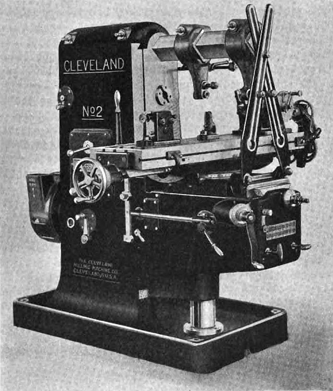 1921 Clark-Mesker Co., #2 Cleveland Horizontal Milling Machine
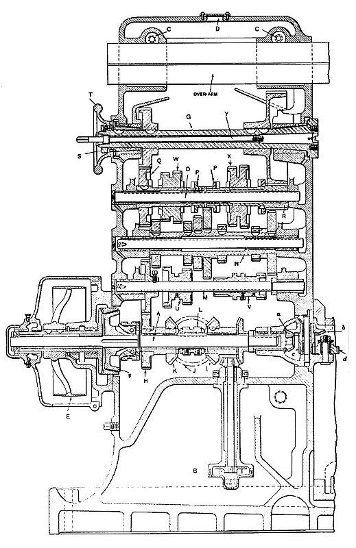 1921 Clark-Mesker Co.-#2 Cleveland Horizontal Milling Machine (Sectional View) Fig. 1
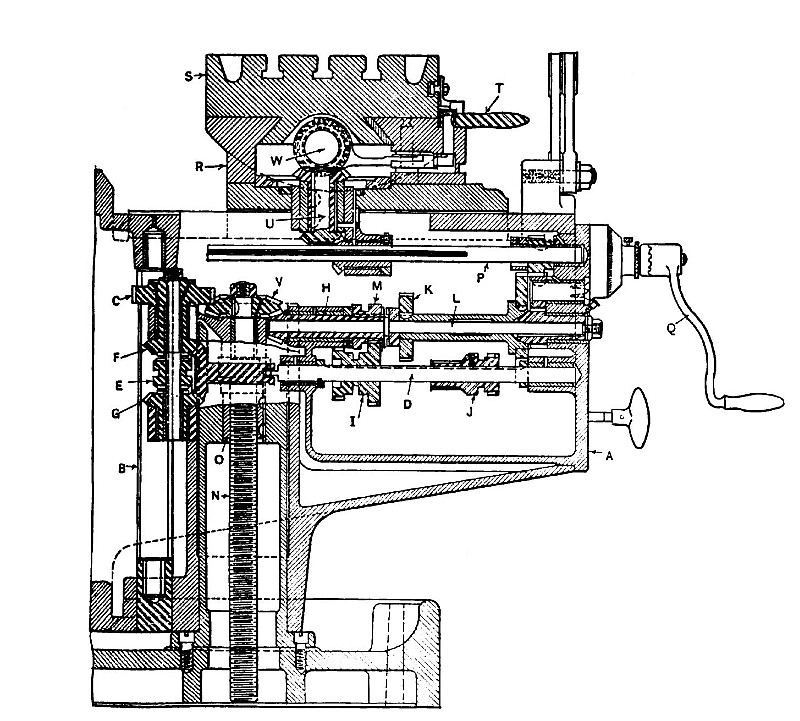 1921 Clark-Mesker Co., #2 Cleveland Horizontal Milling Machine (Sectional View) Fig. 2
|
|