|
Title: |
1871 Article-Henry L. Beach, Spiral Spring Scroll Saw Machine |
|
Source: |
Manufacturer & Builder, V3, Nov 1871, pg. 248 |
|
Insert Date: |
2/26/2017 11:36:11 AM |
New Improvements in Scroll-Saws
With the gradual advance of the modern ornate and elaborate furniture into public favor, and the consequent decline of the old-fashioned, simple, and plain method of ornamentation, tools which would produce the differently curved and manifold parts of the former have become more and more needed. The ordinary broad-bladed saw, as can he readily apprehended, was found inadequate for the purpose, and its place was filled by what is now known as the scroll-saw, which, although first used solely by hand, has, since the introduction of steam in our workshops, been driven almost entirely by that motor.
In the first machines devised for scroll-sawing, it will be found that the blade of the saw is held in a kind of frame similar to that used to hold the large saws employed in the mills. As it became necessary, in order to economize time, to drive these machines with great rapidity, it was found that a considerable loss of power, besides much shaking and consequent weakening of the different parts, was duo to the momentum of this heavy and cumbrous frame, and the attention of inventors was directed to a means of obviating this defect.
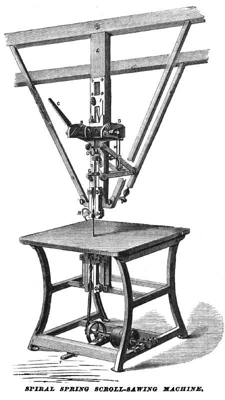
Our figure represents a machine for scroll-sawing, in which it will be noticed that the above-mentioned frame is entirely absent. The blade of the saw is simply pulled downward by a crank under the table, while a steel spiral spring above draws it upward and keeps it well stretched. These springs are represented in our engraving by A A. Each contains 10 coils of 1/2 or 5/8 round steel rod, one being a right-hand, the other a left-hand coil. One end of each of these springs is firmly fastened to the ratchets B B, the opposite ends to the front end of the lever F, which is supported upon the shaft passing through the centre of the springs, and so constructed that there is no friction whatever upon any part of the springs when in motion. The link H, which is of iron, connects the upper lever F with the lower lever G. These levers are so connected that when the saw is moving a 5-inch stroke, the first coils of the springs A A move but 1/10 of an inch, the second coils but 9/100 of an inch, and so on down to nothing, making the average movement of the coils but 1/90 of an inch. The upper crosshead which carries the top of the saw is firmly connected to the lever G, thus making a positive connection between the saw and springs. This insures a perfectly rigid strain on the saw. By means of the ratchets B B and lever C any amount of strain can be given from 10 to 100 pounds, according as it is a small or large saw. This is done by taking hold of the lever C, which is inserted into the side of the ratchets B B, and thus winding or unwinding the springs A A. Each spring and ratchet is independent of the other, so that one or both springs may be used. The tension on the saw by this means can be changed in a moment—while the machine is in motion. A plunger-pump is attached to the inside of the iron plate O D, with a rubber pipe running to the saw, and is worked by the motion of the lever G. The two springs, with all their connections, are permanently fastened to tho iron plate D D, which is raised or lowered to suit any length of saw by means of the crank E, and held in position by the thumb-screw O. In cutting thick hard wood, the saw can be firmly fastened at the bottom, so as to make the crank drive it both ways, relieving the springs, and requiring no more tension to cut 4-inch hard Wood than 1-inch pine. The saw is hooked on top and bottom, which enables the operator to remove it instantly, thereby saving a large percentage of time wasted on other machines in removing the saw where it is firmly fastened at the bottom; also, in removing the support back of the saw, in taking out the pieces cut off on inside work. The advantages claimed are: Its high rate of speed, which is from 1000 to 1200 per minute without jar; the strength and durability of the two springs employed, giving from 10 to 100 pounds' strain on the; saw, while the average movement of the coils is but 1/90 of an inch; the motion of the springs being so slight, the variation in the tension on the saw is less than 1/4 of a pound, thus enabling the lightest saw to be run without breaking; the raising and lowering of the springs with all their connections, thus bringing the lifting power of the springs directly to the top of the saw, no matter what its length; the simple and complete mode of changing the tension of the saw, which is done as above described in a moment of time, without stopping the machine; the construction of the springs and their connections with the saw is Bo arranged as to bring the strain of the saw in a direct line with the bolt fastening the machine to the joist overhead, so that if the three braces shown in the cut are removed and left suspended upon one single bolt, it does not shake enough to jar the saw-dust anywhere on the machine, when running 1000 motion. This machine is in use in different shops in this city and neighborhood, and is giving great satisfaction. It was invented by Mr. Henry L. Beach, and may be seen in operation at his office, No. 90 Fulton street, in this city, and also at the Fair of the American Institute. |
|
 1871 Henry L. Beach, Spiral Spring Scroll Saw Machine
|
|