|
Title: |
1908 Article-LeBlond, R. K., Machine Tool Co.-Heavy Reducing Lathe |
|
Source: |
Southern Machinery, V7, May 1908, pg. 27 |
|
Insert Date: |
6/28/2017 1:19:52 PM |
R. K. LeBLOND MOTOR DRIVES
The R. K. LeBlond Machine Tool Co., Cincinnati, Ohio, furnish lathes and millers with a drive suitable for either variable or constant speed motors, so that LeBlond tools may be had equipped with motors, controller, etc., complete, or where a customer prefers to furnish electrical apparatus provision is made for motor and controller. Motor drive might be divided into classes, viz., the group system and the individual drive, in which each tool is driven independently by a motor. Under certain conditions each system has special advantages over the other; however, the individual motor-drive is the only one considered at present. The large number of speeds obtained, usually about sixty on LeBlond tools, enable the proper cutting speed to be had for every class of work, resulting in increased quantity and also an improvement in the quality of the work.
With the LeBlond patent friction back gears, furnished on motor-driven tools and with the speed changes on the controller, any one of forty speeds are obtainable in any ratio as high as 9 to 1 while the machine is running. The use of the individual motor permits each machine. to be placed where it is wanted, resulting in increased output, due to the added facility of handling the work, also to the elasticity of the whole arrangement for adding tools and changing them when necessary. The modern practice of serving all machine tools with a crane, especially those of the larger sizes, is simplified by the freedom from overhead shafting, hangers and belts. Individual tools can be run on overtime work without waste of power and expense of running the entire line shafting. Power may readily be obtained from a local company or adjacent concern, in case of breakdown. No entire group of tools can be put out of use as when using line shafting, and the increased light and freedom from dirt has much to do with the character and output of the work.
As an example of the economy which may be obtained of the electric drive the company gives the results obtained in facing off a plate 30 inches in diameter, with one-inch hole, on a 30-inch lathe: with 5-step cone and single speed countershaft, giving 10 changes of speed. For convenience, a cutting speed of 44 feet was used. The total time taken was: Motor, 21.38 minutes; double countershaft, 24.34 minutes, and with single countershaft, 27.10 minutes.
The lathe was running in back gear, the last cut taken at a reduced speed, as it would require less time to complete the job in this manner than it would to change from back gear to open belt.
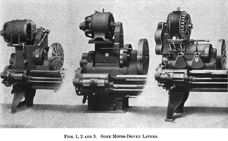
This shows a saving of 10 per cent for the double friction countershaft, and 21 per cent for the motor drive, over the single countershaft. Ideal conditions are represented and it does not allow for time required in making changes, and takes for granted that these are made at exactly the proper time. The mechanical speed changes are closer than ordinarily found. The company claims a greater saving would be effected in turning work of a given diameter. The illustration, Fig. 1, clearly shows the arrangement of the gearing employed for variable speed drive on all lathes up to and including 22-inch swing. The headstock has pads cast on the sides planned to receive the motor housing or frame that supports the motor. A plate is inserted between the motor and the housing which is made to fit the motor feet on one side and the housing on the other. The drive from the motor is through the clutch pinion on the motor shaft and the rawhide intermediate gear which drives the sleeve gear that is mounted on the spindle. The sleeve gear can be locked to the face gear for direct speeds, or the drive can be had through double friction back gears.
This arrangement gives three mechanical changes to the tool, independent of the motor. All gears are protected by covers which allow easy access for cleaning, inspecting, etc., and in no way, interferes with the adjustment of the spindle and boxes. The motor drive is through a friction clutch operated by a lever close to the operator, for quick starting and stop lower voltages are not required, resulting in a more powerful drive or permitting the use of a smaller motor. On lathes requiring greater speed range the construction is somewhat modified, as in Fig. 2. In this case the rawhide gear drives a double friction shaft mounted in the motor housing above the spindle. This gives all the features previously described and four mechanical changes of speed in addition. Fig. 1 is an extra heavy 24-inch high-speed lathe. The lathe is built either as a high-speed reducing lathe, as shown, for taking heavy reducing cuts on steel bars and forgings, or as a high-speed engine lathe. The spindle has a 23-16-inch hole and runs in Babbitted bearings. The front journal is 5 3/8 inches diameter by 9½ inches long. There are 30 speed changes, ranging from 11.2 to 143 on the reducing lathe. and from 7.6 to 250 on the engine lathe. The motor drive is through a rawhide intermediate gear. The motor pinion has a friction for quick starting and stopping, and there are four mechanical changes of speed, and quadruple back gears. An improved design of tail stock is used with the front end of the barrel reinforced, and improved method of clamping the spindle to the bed. The apron has steel gears throughout, is semi-box construction, and all shafts and studs, are supported at both ends, the rear bearing acting as a rib to connect the ends of the apron. A quick-change device is provided for feed and screw cutting. This arrangement gives 33 threads and feeds, including 111½ pipe threads, without removing a gear. A controlling lever for the motor is located on the carriage, and a graduated index dial is on the vertical shaft. Connection with controller is made by a chain and sprocket on the end of the spindle shaft. The lathe can be operated entirely from this shaft, or speed can be set at required rate and the lathe quickly started and stopped with the lever operating the friction in motor pinion. For constant speed drive the motor is mounted on the headstock and the drive is through a rawhide intermediate gear to the shaft on which are mounted the double friction gears. This gives two changes of speed as well as means for quickly starting and stopping the lathe, independent of the motor. The lower shaft contains a set of sliding cone gears, giving a total of twelve changes. There are no back gears or lock-nut to be engaged, and the entire range of speed can be obtained while the lathe is running. All gears are made of steel, the teeth have beveled edges and are hardened. Those running at a high periphery speed are engaged with a clutch. |
|
 1908 LeBlond, R. K., Machine Tool Co.-Some Motor Driven Lathes
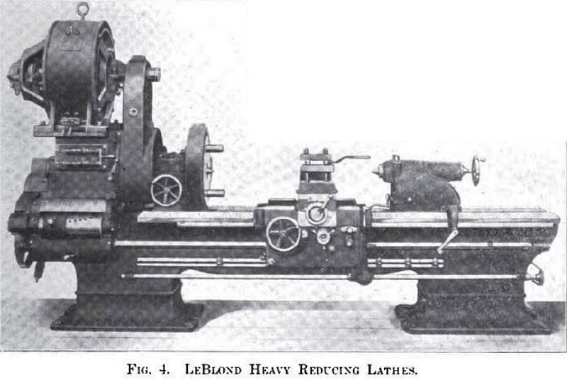 1908 LeBlond, R. K., Machine Tool Co.-Heavy Reducing Lathe
|
|