|
Title: |
1916 Article-Bond Foundry & Machine Co.-Bowen Milling Machine Fig. 2-4 |
|
Source: |
Machinery Magazine, V22, Jun 1916, pgs. 913-914 |
|
Insert Date: |
6/14/2018 8:16:40 PM |
Bowen Milling Machine
It will be seen that this machine may be used for either vertical or horizontal milling, but it was especially designed for the performance of various thread milling operations. A feature of the design is that the machine does not require a special lead-screw for each pitch of thread to be cut. The vertical position of the table is fixed and adjustment for depth of cut is secured by moving the cutter-head on its bearings on the column. Lateral adjustment is obtained by moving the cutter-head column in or out from the table; and the table is traversed by a lead-screw.
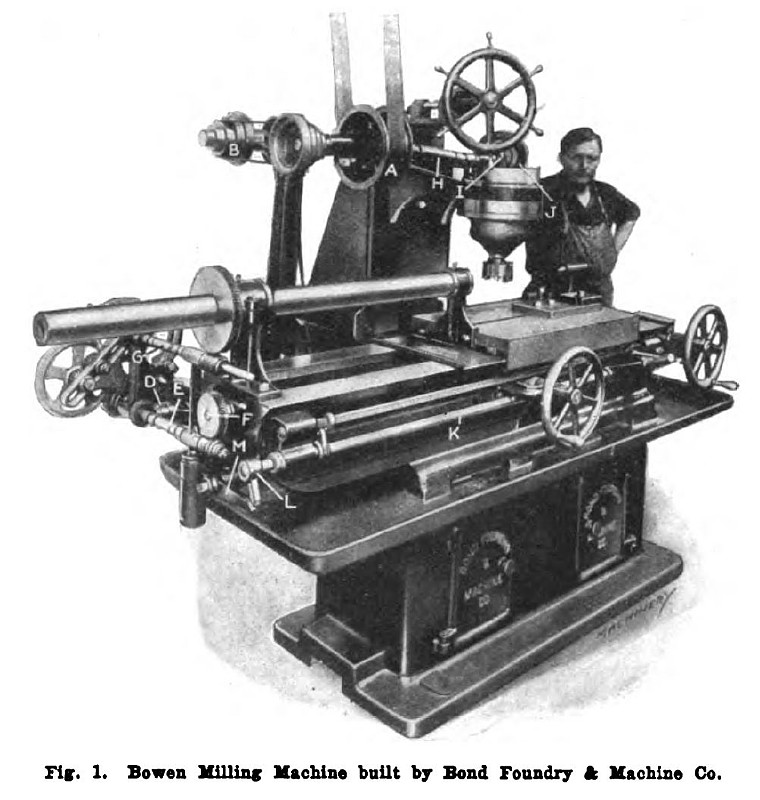
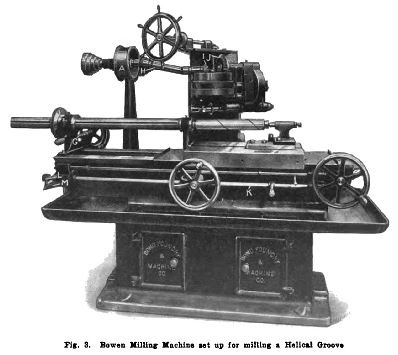
The Bond Foundry & Machine Co., Manheim, Pa., has perfected and placed on the market the Bowen milling machine illustrated herewith. This machine was designed by James E. Bowen, mechanical engineer of this firm, who was formerly with the Milled Screw Co., Sayre, Pa. While this is a universal milling machine, in that it can be used for vertical or horizontal milling of almost any type. it is particularly adapted for thread milling; and Fig. 3 shows the machine set up for milling a helical groove. Unlike many thread-milling machines, it does not require a special lead-screw for every pitch of thread to be cut.
The table of the Bowen milling machine is nonadjustable vertically and runs upon a bed that is cast integral with the base. The base is made very broad and heavy, and it is claimed that much of the vibration incident to operation is absorbed in this heavy base. Adjustment for depth of cut is secured by moving the cutter head vertically on its hearings on the column by operating the pilot wheel at the front of the machine. Lateral adjustment is made by moving the cutter-head column in or out from the table on ways on the machine base, this adjustment being controlled by the operation of the handwheel beneath the table. The table of the milling machine is traversed by a lead-screw that receives motion through a worm and worm-wheel, leading back to the driving mechanism. The table has a maximum longitudinal travel of 4 feet, and automatic stops are provided to limit the movement in either direction. A handwheel at the extreme right-hand end of the machine provides for traversing the table by hand.
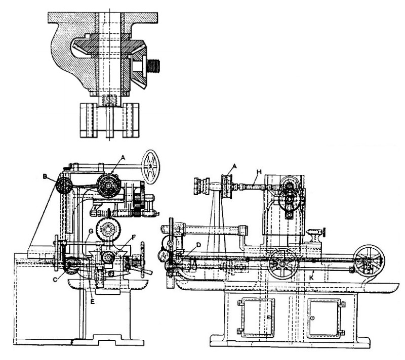
The entire operation of the machine is controlled from driving pulley A, which may be seen near the center of the machine. Rotation is carried back to shaft B. and thence down to a secondary driving shaft C that terminates, as may be seen in Figs. 1 and 4, in a bevel gear D. This bevel gear transmits motion to worm-shaft E that carries power to the worm-wheel F, which operates the carriage through a lead-screw. From the opposite end of worm-shaft E, a spur gear carries rotation through a set of change-gears to the worm-shaft G that operates the work-holding spindle. This mechanism may best be seen by referring to Fig. 1 in connection with the line illustration Fig. 4.
From the main driving shaft, rotation is carried to the cutter-head as shown in Fig. 3 by a universal joint connection H. By means of gearing, motion is carried from this universal joint shaft to the cutter-arbor, and at the same time a speed reduction is made in the ratio of 9 to 1. On the cutter-head is a bevel pinion that receives rotation from the small bevel pinion I, and transmits it through the larger pinion J. This arrangement permits the cutter-arbor and gearing to be swiveled to any angle in the horizontal plane. From the shaft on which gear J is mounted, a spur pinion meshes with another spur gear that carries rotation down to the cutter-arbor. From worm-shaft E, brackets support the spindle worm-shaft G, and when the worm on the lower shaft is disengaged, the upper one also is disengaged. The worm-disengaging mechanism is operated through a hand-lever on rod K at the front of the machine. The rocking of this shaft causes finger L to operate lever M and thus raise or lower the two worm-shafts to engage or disengage the two worms.
By making the proper changes in the spur gears at the rear of worm-shaft E, a helical groove may be cut of any desired pitch from a key-seat to the finest thread. It is obvious that the work-holding spindle may be fitted with any form of chuck or faceplate, and that the table is provided with a tail-center for supporting long work. Fig. 1 shows the machine set up with a vertical attachment on the cutter-head for face-milling; and the design of this cutter-head may be seen in Fig. 2 which illustrates this mechanism in cross-section. The drive is from the same spindle that operates the cutter when working on thread milling. Rotation is received from the bevel gear on the right-hand side, as viewed in Fig. 2, and meshing with this pinion is a bevel gear on the vertical cutter-spindle. Cutters up to 10 inches in diameter may be used. |
|
 1916 Bond Foundry & Machine Co.-Bowen Milling Machine Fig. 1
 1916 Bond Foundry & Machine Co.-Bowen Milling Machine Fig. 3
 1916 Bond Foundry & Machine Co.-Bowen Milling Machine Fig. 2-4
|
|