|
Title: |
1875 Article-J. & F. Howard, 8 H. P. Farmer's Steam Traction Engine |
|
Source: |
Engineering, V20, 16 Jul 1875, pg. 48 |
|
Insert Date: |
8/16/2018 1:15:20 PM |
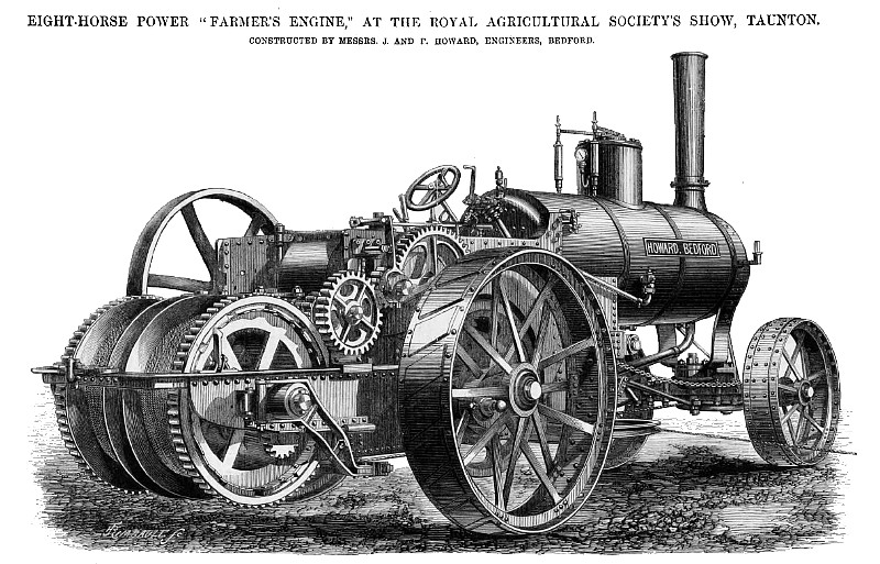
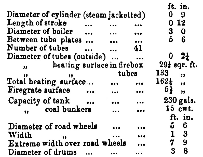
Messrs. J. and F. Howard are represented in the class of exhibits with which we are now dealing by a 16-horse ploughing engine and 8-horse power “farmer’s engine", of the letter of which we give a perspective view on page 48. Like those which Messrs. Howard have for some time past been building, this engine is arranged so that the engine proper is distinct from the boiler, the cylinder, crankshaft bearings, &c., being carried by the frame behind the firebox. In their former engines Messrs. Howard placed the cylinder at the rear, thus necessitating a somewhat long steam pipe, but in the type we are now describing this has been improved, the cylinder being now steam jacketed and placed next the firebox, the crankshaft being of course now placed at the hind end. The two-rope drums vertically run on a shaft carried by a continuation of the engine frame to the rear, and the arrangement of the gear by which they and the road wheels are driven can he readily traced out from our engraving. The rope drums are fitted with coiling gear for guiding the rope, as shown. This arrangement makes a very long engine, and as we have stated on former occasions we do not consider that the ordinary plan of fixing a cylinder to the boiler is attended with sufficient disadvantages to render it worthwhile to depart from it, whilst it certainly has important advantages. Messrs. Howard, however, prefer the system of fixing the cylinder on an independent framing, and the present engine is an embodiment of their latest plans. The principal dimensions of the engine we illustrate are as follows: (see table)
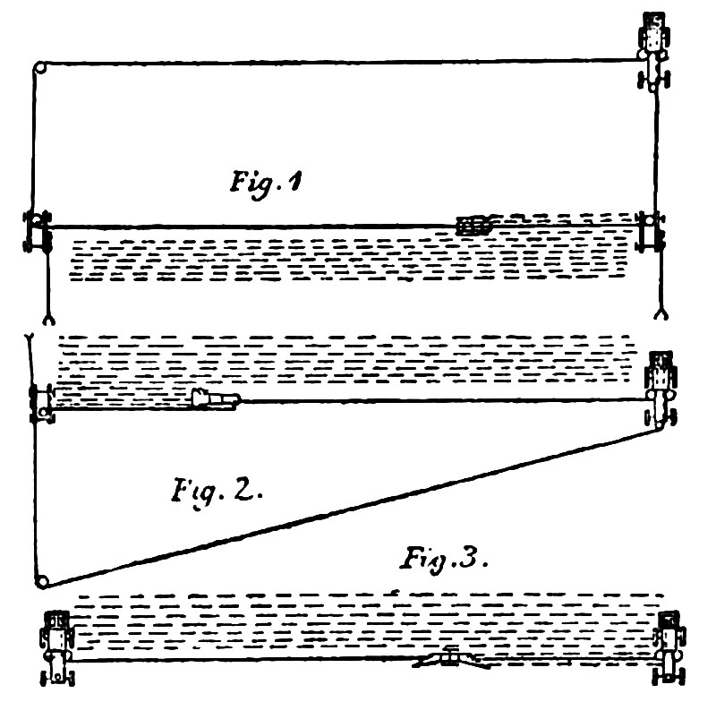
These engines are also intended to be worked either in connection with roundabout tackle, as single engines with self-moving windlass, or in pairs on the double-engine system. These three modes of working are illustrated by the annexed diagrams, Fig. 1, 2, and 3 respectively. In the arrangement shown by Fig. 1 the engine really forms a steam windlass, of which the drums are driven entirely by spur gear. We should add that the windlass is so mounted upon the engine, that it can be dismounted at the end of the ploughing season, so that the engine may be relieved of its weight when used for ordinary traction purposes. The engines have steel gearing, and are well made. |
|
 1875 J. & F. Howard, 8 H. P. Farmer's Steam Traction Engine
 1875 J. & F. Howard, 8 H. P. Farmer's Steam Traction Engine (Table)
 1875 J. & F. Howard, 8 H. P. Farmer's Steam Traction Engine (Figs. 1 & 2)
|
|