|
Title: |
1911 Article-Warner & Swasey Co., Universal Lathe Turret |
|
Source: |
Machine Tools Commonly Employed In Modern Engineering Workshop, V1, 1911, pg. 61 |
|
Insert Date: |
7/25/2020 9:59:18 PM |
As already stated, one of the most essential features of the screw machine is the turret, in which the turning, boring, tapping, and other tools, required for the various operations, are set up in position and in their correct order. The turret or capstan is rotatably mounted upon a slide, which moves in corresponding grooves in the turret saddle, clamped upon the shears of the bed. Six different tools can be mounted in the holes in the capstan, and binder bushes are provided for securely holding the tools in position. When the capstan slide is moved backwards, by suitably rotating the large star hand-wheel, the locking bolt, which accurately positions the turret, is withdrawn, and a further backward motion of the slide causes the turret to rotate until the next tool is in position, when the locking bolt once more fixes the position, as the slide is advanced to bring the tool up to the work. The locking bolt referred to is situated at the extreme front end of the slide, directly under the cutting tool; and as the accuracy of the alignment depends upon the good condition of this bolt, it is made to engage with steel taper bushings attached to the underside of the turret at nearly its full diameter. While the tool is in operation the capstan is clamped in position on the slide by means of the hand lever on the capstan spindle, shown in the illustration.
Upon the rear end of the slide is mounted a rotatable head carrying six adjustable screwed stops, one corresponding to each of the capstan positions. When the capstan is rotated into a new position, this head is correspondingly rotated, and the travel of the slide is then limited by the adjustable stop, which engages with a fixed projection on the saddle. The travels of the various tools, and therefore the sizing of the work, is determined by the setting of these stops, and in this way the frequent use of micrometers or gauges for measuring the work is avoided, with a consequent saving of time. Means are provided for adjusting the alignment of the tool holes in the turret to suit the spindle centre. Thus, to adjust the height, the turret saddle is mounted upon a supplementary taper base; and taper gibs, fitted along the whole length of each side of the saddle, provide the necessary side adjustment of the slide.
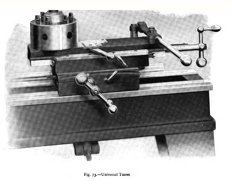
Fig. 73 represents a universal turret, which can be mounted upon the bed of an ordinary engine lathe. In this arrangement the slide is operated by a simple hand lever, shown at the right end of the slide, and also by means of a hand screw, shown at the extreme right of the illustration. The turret itself is rotated by hand into the various positions, and the positioning bolt is controlled by the small lever projecting from the slide. Swivel and set-over adjustments are provided, as indicated, and graduated dials and scales are fitted to facilitate the adjustments. In addition, a fitted centre stop is provided for instantly setting the turret in correct alignment with the spindle centre. It will be seen that in these slide designs the turret overhangs the saddle when the slide is advanced, and that, on heavy work, a certain amount of spring is to be expected under such conditions. This objection is not of serious importance on the lighter classes of work, for which these machines are chiefly intended, and the convenience and rapidity of the arrangement fully justify its use. |
|
 1911 Warner & Swasey Co., Universal Lathe Turret
|
|