|
Title: |
1911 Article-Alfred Herbert, Ltd., #9 Capstan Lathe Saddle Apron & Gear Box |
|
Source: |
Machine Tools Commonly Employed In Modern Engineering Workshop, V1, 1911, pgs. 68-69 |
|
Insert Date: |
7/31/2020 1:45:19 PM |
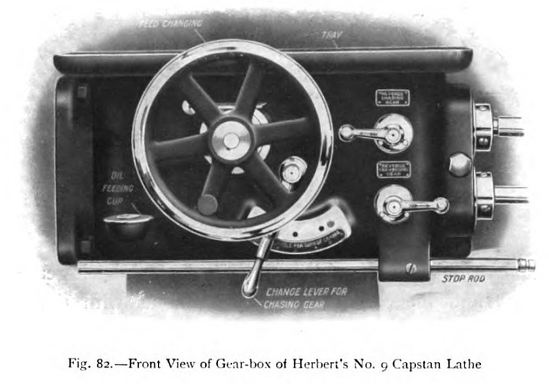
Torsional rigidity of the bed is secured by enclosing it at the top and bottom, with the exception of the necessary holes for extracting the core, and these holes are strongly reinforced. There are no long slots through the top or bottom members for bolting down the capstan bed, and the use of the rigid box girder section is therefore possible. At the headstock end the bed is supported upon a cabinet, which at the foot is cast in one piece with an oil pan which collects any oil that may run down from the head, and which also gives the necessary width of support under the heaviest end of the machine. At the other end the bed is supported upon a lighter double leg. The lathe saddle can be traversed rapidly by a handwheel and rack-and-pinion gear, in the ordinary manner, or by power. It is provided with a chasing arrangement consisting of a leader and nut, the leader being driven by gearing in the feed box. By changing the leaders and nuts, and by suitably varying the feed -box gear ratio, a large range of threads can be cut, the range being sufficient to cover all the most useful pitches. Three gear ratios of 1, 2, and 4 are provided in the feed-box, and these can be readily inserted by placing the chasing lever on the face of the gear-box (fig. 82) in one or other of its three positions. With a standard set of seven leaders and nuts, in conjunction with these feed ratios, a series of twenty-one threads, ranging from four threads per inch to twenty-eight, can be readily cut. Other threads can, of course, be cut with the chasing gear by using special leaders and nuts of the required pitch. A taper attachment enables both internal and external taper threads to be cut with the same ease and accuracy as parallel threads, and right- or left-handed screws are cut by reversing the motion of the leader, the reverse chasing-gear lever being clearly indicated in the general view of the feed-box.
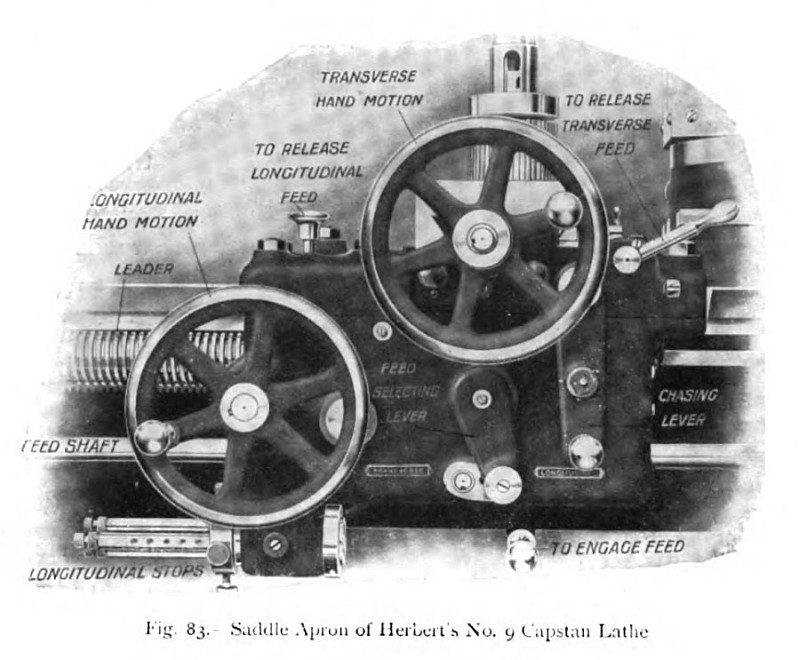
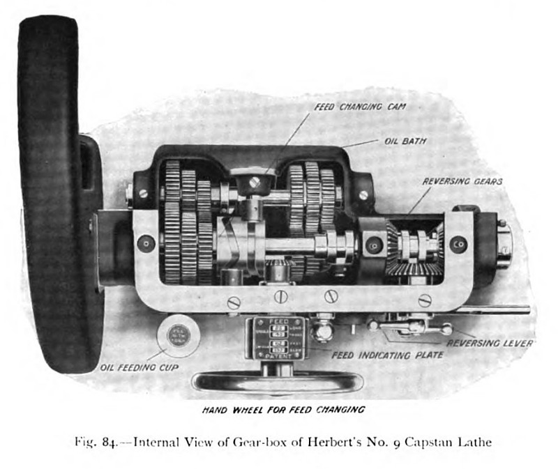
A general external view of the saddle apron, with the principal parts indicated by name, is given in fig. 83. The double-ended chasing lever controls the nut, and the arrangement is such that, as the nut is disengaged from the leader screw, the chasing tool is withdrawn simultaneously from the work, while the position of the leader remains unaffected. When the nut is re-engaged the tool returns again to its correct cutting position, and the additional depth of cut is independently applied by operating the cross-feed handwheel, which is fitted with an adjustable graduated index disk. The cross-feed screw can thus be reserved for applying the cut, as the actual withdrawal or return of the tool is affected by the motion of the chasing lever. This arrangement makes it unnecessary to rotate the cross-feed screw in the reverse direction and disturb the setting of the index, which only needs to be advanced, at the completion of each successive travel, by the amount of the cut desired. For ordinary feeding requirements the saddle is moved longitudinally, and the cross saddle transversely, by means of the customary feed-shaft, driven from the feed-box, the internal details of which are indicated in fig. 84.
On the front of the apron (fig. 83) is mounted the feed selector lever, which connects the feed mechanism to the apron-driving gear or to the cross-slide gear, according as it is swung towards the right
or the left; and below the apron is situated the feed engaging lever, the feed release gear being of the dropping-worm type. As this worm gear is subjected to considerable use, it runs immersed in a bath of oil.
An interlocking arrangement renders it impossible to have, in simultaneous operation, the ordinary feed-gear and the chasing-gear, or the longitudinal feed and the transverse feed, and thus the possibility of damaging the searing is avoided. Means are provided, as indicated in fig. 83, for rapidly releasing the longitudinal and the transverse feeds. For both of these feeds there are provided automatic stops, there being altogether eight stops.
In the case of the longitudinal stops, which are clearly indicated in the various views, the fixed stop mounted on the feed-box is provided with a screw adjustment, which enables all the saddle stops to be set in unison to suit the requirements of the work. |
|
 1911 Alfred Herbert, Ltd., #9 Capstan Lathe Saddle Apron
 1911 Alfred Herbert, Ltd., #9 Capstan Lathe (Front View of Gear-Box)
 1911 Alfred Herbert, Ltd., #9 Capstan Lathe (Internal View of Gear-Box)
|
|