|
Title: |
1905 Article-Thomas Shanks & Co., Vertical & Horizontal Planing Machine |
|
Source: |
Engineering, V79, 02 Jun., 1905, pg. 708 |
|
Insert Date: |
2/27/2021 11:14:23 AM |
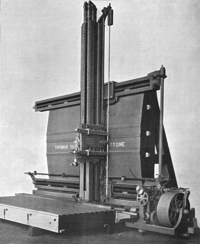
Messrs. Thomas Shanks and Co., of Johnstone, have long been famous for the production of capitally designed and accurate machine-tools of the heaviest description. On page 708 we this week illustrate a very large specimen of their now well-known vertical and horizontal planing machines, recently constructed by them for the Wallsend Slipway and Engineering Company, Limited. This machine has a horizontal stroke of 25 ft. and a vertical stroke of 23 ft., its gross weight being 135 tons. The makers have built over eighty machines of this type in its different sizes during the past few years, and, as experience has accumulated, nave effected from time to time improvements in de tail, with the result that, as now made, these machines will take the heaviest cuts without perceptible yielding of the frames or guides. Slotting, in cutting, and grooving can be done rapidly in steel. The machine will accurately plane surfaces at right angles to each other, with a feed which in finishing cuts may be ½ in. to 4 in. and can be varied in all directions of cutting within very wide limits. Means are provided by which the number of tools at work need never be less than two and may be as many more as the user wishes.
The reverse is made at a high speed and is constant, but by means of change-gears the cutting stroke can be made at any speed best suited to the cut and the material operated on. The tools are mounted on tool bars, three of which are visible, one above the other, in our engraving. They are not placed as they would be when at work, but so as to show how they are fastened when slotting or planing, the lowest bar showing the slotting-tool. By means of angled brackets, which are not shown, but which are fastened to the face of the in-cutting slide, two of these slotting-bars can be placed at a considerable distance apart; and as both brackets and bars are serrated to fit the corresponding serrations on the in-cutting slide, absolute solidity is obtained at a considerable projection when either slotting or planing.
The saddle to which the tool apron is secured is counterbalanced and traverses along the vertical column when the machine is being used for vertical cutting, whilst the column is traversed bodily along the horizontal slides in making a cut in the horizontal direction. The tool-apron can, moreover, be moved in or out from the back of the machine, so that motion to a tool- point is possible in three directions at right angles to each other.
The tappet gear for reversing the motions at the end of a stroke has a rod working in guides instead of mounted on swinging links, as is very frequently the case. At the end it is fitted with a rack working in gear with a segmental wheel keyed to the shaft, by which the reverse is operated. This arrangement economizes space and reduces the number of moving parts requiring to be lubricated.
A machine of a size smaller than that represented in our engraving has been used for machining the castings of the largest turbine yet built. As will be seen, the machine is in no sense a “special” tool, since it is capable of doing every kind of surfacing and slotting work. |
|
 1905 Thomas Shanks & Co., Vertical & Horizontal Planing Machine
|
|