|
Title: |
1911 Article-J. Butler & Co., 14 foot Motor Driven Planer |
|
Source: |
Machine Tools Commonly Employed In Modern Engineering Workshop, V2, 1911, pgs. 44-46 |
|
Insert Date: |
6/22/2021 1:48:55 PM |
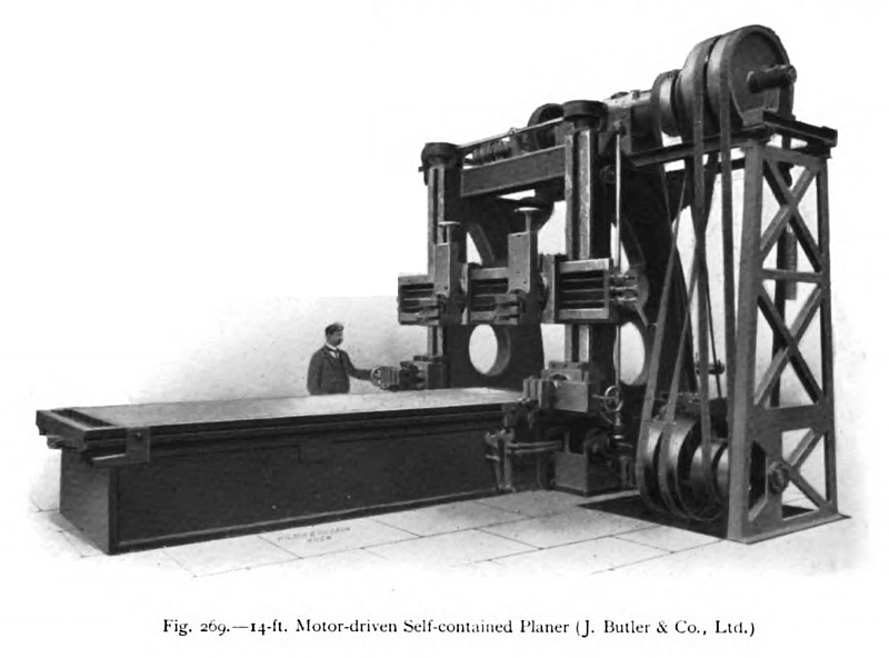
A 14-ft. Motor-driven Planing Machine
A larger 6 ft. x 6 ft. x 14 ft. self-contained motor-driven planer, built by Butler & Co., Ltd., of Halifax, is illustrated in fig. 269, the countershaft being shown mounted on strong girders secured to brackets on the top of the standards. This countershaft arrangement is of particular value when the roof of the shop is low, or when the countershaft cannot be readily mounted above the machine. A general view of the bed, with the rack-driven table removed, is shown in fig. 270, which specially indicates the gearing provided for driving the table. This gearing is so mounted that it can be completely removed for repair without disturbing the main bed, and it will be seen that the shafts carrying the several pairs of reducing gears are very short and rigidly supported, thus reducing the effects of torsion and vibration. On the same illustration are clearly indicated the V guides, upon which the table moves, and the oiling pockets and the rollers, which are pressed upwards in contact with the running surfaces by means of springs. To machined faces on the sides of the bed, which has a length of over two and a half times the travel, are bolted the box-section uprights, the latter being securely braced together at the top.
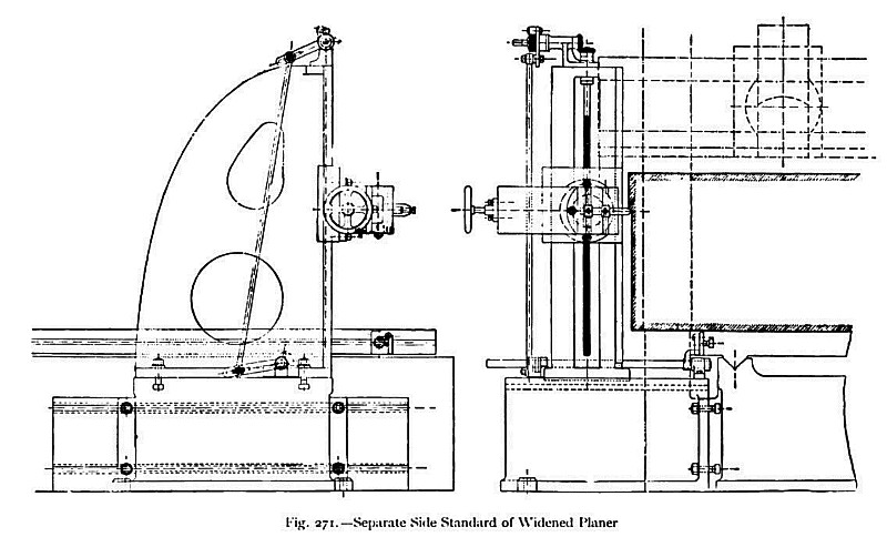
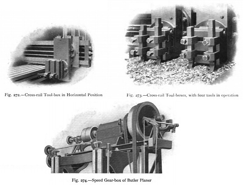
For planing the ends of long pieces of too great a width to pass between the uprights, a separate side standard may be employed. In such cases the standard is set up in position on a detachable base secured to the side of the bed, and arrangements are provided for adjusting the standard longitudinally. Thus, the standard may be worked in a position close to or away from the cross slide, according to the requirements of the work. If the piece is too heavy or unsuitable for mounting upon the table, it may be secured to the fixed base and the standard with the cutting tool mounted on the moving table. Self-acting vertical-feed motion is communicated, in any position, to the tool-box of the standard by means of a rod connected to the ratchet and operated by dogs. This method of increasing the width capacity of the planer is illustrated in fig. 271, which also shows the feed mechanism referred to above. On the cross slide are mounted two tool-boxes adjustable by power or hand in both horizontal and vertical directions. The tool - box is provided with a circular seating, and can be set in any inclined position, or horizontally for operating on the side of the work. Fig. 272 shows the latter arrangement of the tool-box, and fig. 273 shows both boxes situated in a vertical position, close together on the cross slide, with four tools in simultaneous operation. Other arrangements, with the side tool-boxes mounted directly on the side uprights, can also be provided. For driving the large machine illustrated, two narrow open belts and two narrow crossed belts are employed, instead of single wide belts. Some saving in power results from the use of light high-speed belts, and the time required at the end of the strokes for shifting the narrow belts is reduced. The striking levers, by means of which the belts are shifted from the fast to the loose pulleys, are operated by a cam mechanism specially designed to reduce the power customarily required for the reversal of such machines.
If a planer has to deal with a variety of different metals it is desirable to have a choice of several cutting speeds; and frequently variable-speed gear-boxes are provided, as illustrated in the partial view (fig. 274). In this particular arrangement, provision is made for three cutting speeds and one constant quick-return speed. The gears are so arranged that the wheels of only one set are in mesh at one time, and the keys along which the gears slide are forged solid with the shafts. The whole mechanism is entirely enclosed and runs immersed in oil. Other variable-speed motor or countershaft driving arrangements can be used, instead of the gear-box referred to above. |
|
 1911 J. Butler & Co., 14 foot Motor Driven Planer
 1911 J. Butler & Co., 14 foot Motor Driven Planer (Side Views)
 1911 J. Butler & Co., 14 foot Motor Driven Planer (Cross Rail & Gear Box)
|
|