|
Title: |
1911 Article-Jones & Lamson Machine Co.-Roller Feed Chuck & Flat Turret |
|
Source: |
Machine Tools Commonly Employed In Modern Engineering Workshop, V1, 1911, pg. 84-85 |
|
Insert Date: |
4/18/2022 1:41:52 PM |
|
Upon the outer end of the spindle is mounted the roller-feed mechanism, illustrated in figs. 109 and 110. This gear is put into action by the same lever that opens the automatic chuck, and thus the rod is only fed forward when the chuck jaws are open. The feeding of the stock takes place while the lathe spindle is running The outer shell is mounted rigidly upon the hollow spindle, and therefore rotates with it and with the work, which is kept in a central position within the spindle by means of a scroll chuck, shown at the right end of the feed mechanism. The rolls, which feed the rod forward, are mounted upon the shell in carriers, which provide substantial bearings on both sides of each roll, as indicated by the ghost outline of fig. 109. They can be adjusted to or from one another to suit the diameter of the stock, against which they are pressed by means of the springs shown in fig. 110, and the rotation of the rolls is effected by means of the worm and worm-wheel gearing shown in the figure. Thus, if, while the spindle and the roller-feed mechanism are rotating, the spiral-toothed wheel shown the right end is clamped and prevented from rotating, the two worm shafts will commence to revolve and drive the four worm wheels on the roller spindles. The stock bar will then be fed forward until the toothed wheel is released, when the rotation of the rollers will cease. A general section of the machine, through the spindle and through the saddle, is given in fig. 105, and the external appearance of the turret itself is represented in fig. 111. From these views it will be seen that the turret is a simple flat circular plate grooved on the top surface to take the various special tool-holders, which will be described later. It is accurately fitted to a seating turned on the face of the carriage and is held down by an annular gib. The carriage is mounted upon the V's of the lathe bed, and is kept in position by gibs, which bear on the underside of the projecting edges of the bed. It will be seen, therefore, that the distance between the turret plate, on which the tools are mounted, and the bed of the machine is very small, and that the most rigid support of the tools is obtained, more especially when compared with the commonly used multiple-slide arrangements, in which the number of the parts used is considerably greater. Immediately under the working-tool position is situated the indexing pin, which securely locks the turret plate when each tool is in line with the bed. This pin is shown in the general section, fig. 105, from which it will be seen that the pin is in the best position for holding the tool rigidly. When the carriage is moved backwards, by suit- ably operating the large star handwheel at the front, the turret is automatically turned into the next position, of which there are six, and the mechanism can be adjusted to turn the turret as soon as the tool is clear of the work. By raising and lowering trip screws, placed near the centre of the turret, the latter may be turned past tool positions that may not be in use. Along the bed of the machine are arranged twelve adjustable stops, which control the longitudinal travel of the carriage. Corresponding with each of the six positions of the turret, there are accordingly two longitudinal stops. Both the turret slide and the cross headstock are power-fed through a speed varying device, which is conveniently controlled by the handwheel, marked “speed variator” in the general view, fig. 104. One revolution of the handwheel gives the complete range of feeds, varying from the fastest drilling speed of 100 per inch, to the coarsest turning speed of 10 per inch. On the feed rod there is a spring arrangement, which yields when the cutting pressure exceeds a predetermined amount, and thus the uniformity of the cut is ensured, and more particularly when turning up to a shoulder. When the turret carriage reaches a stop it is held against it by the pressure of the spring arrangement, already referred to, until released by the operator, and the carriage therefore cannot spring back before the shoulder has been accurately and smoothly faced to size. |
|
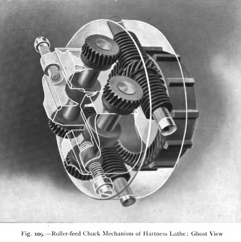 1911 Jones & Lamson Machine Co., Roller Feed Chuck Mechanism
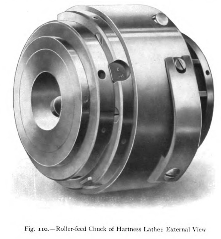 1911 Jones & Lamson Machine Co., Roller Feed Chuck, External View
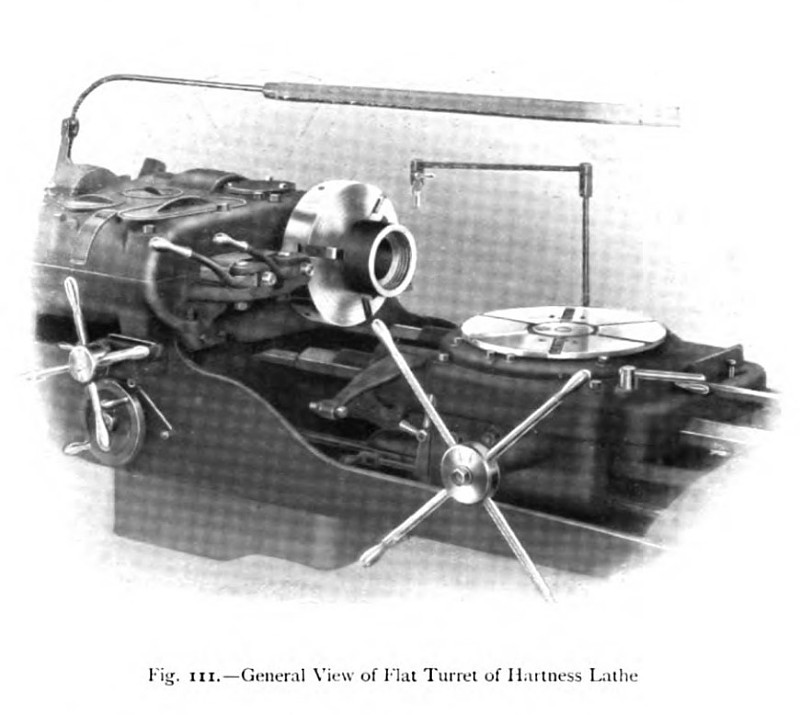 1911 Jones & Lamson Machine Co., Flat Turret
|
|