|
Title: |
1911 Article-Alfred Herbert, Ltd., #1 Automatic Screw Machine |
|
Source: |
Machine Tools Commonly Employed In Modern Engineering Workshop, V1, 1911, pg. 99 |
|
Insert Date: |
5/4/2022 6:52:18 PM |
|
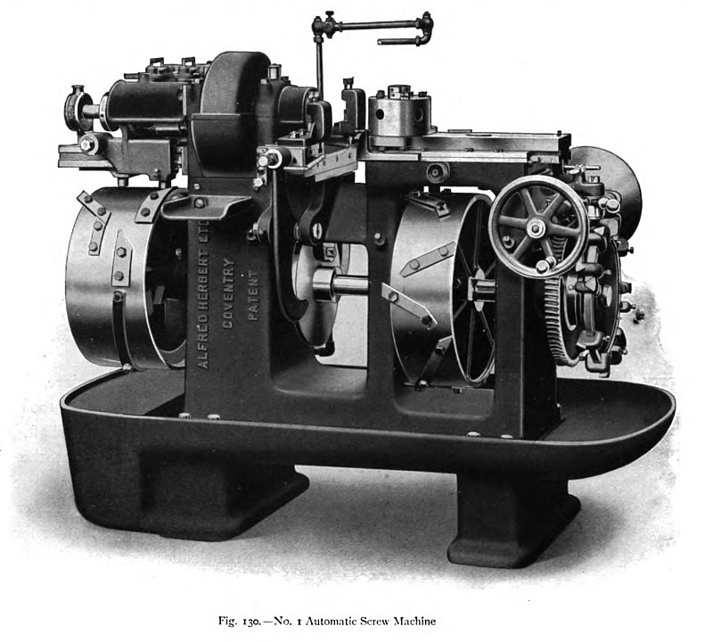
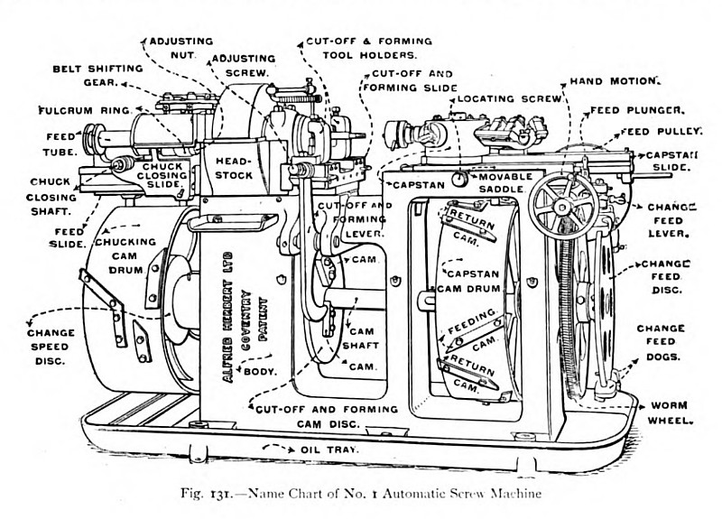
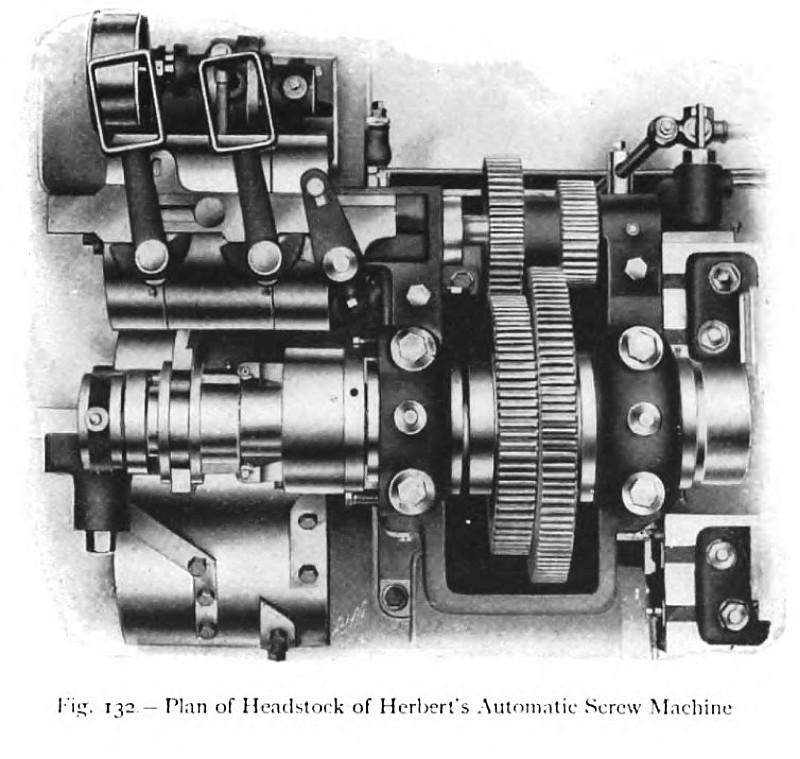
Messrs. Alfred Herbert, Limited, manufacture their standard automatic screw machine in eleven sizes, which deal with bars up to 3½ in. diameter in the largest (No. 14) machine, and down to 3/8 in. in the smallest (No. 00). A general view of the No. 1 automatic screw machine is illustrated in fig. 130, and an outline drawing of the machine, with the principal parts named for reference purposes, is given in fig. 131. This particular size of machine is capable of dealing with rod of a maximum diameter of 1 in. The maximum length that can be turned is 3¼ in., and the greatest length of the article produced is 3¾ in. It will be seen from the illustrations that the main frame of the machine upon which the mechanism is mounted is a strong and rigid, hollow, dry-sand casting; the strength being sufficient to prevent any deflection of the essential parts, and thus to ensure the production of accurate work even when taking heavy cuts. The frame is supported in a large tray, provided with the usual oil well and strainer, situated within the left support. Upon the left upright portion of the frame is mounted the hollow spindle headstock with its driving and feed gears, and the right-hand frames carry the capstan slides and cam driving mechanism. A stout crosspiece, binding these main uprights together, serves to carry the cut-off and forming tool-slide. Longitudinally through the body of the machine there runs the cam shaft, upon which are mounted, at the right end, the driving worm wheel and change-feed disk; the capstan cam drum, situated under the capstan slide; the cut-off and forming cam disk, near the middle of the length; and the chucking cam drum, at the extreme left end of the shaft. Two sets of belts are required for operating the machine, one for driving the headstock, and the other, at the right end, for driving the cam shaft. The hollow spindle of the headstock is driven through reduction gearing from a back shaft, upon which are mounted the driving pulleys, shown in the plan of the headstock, fig. 132. This arrangement of reduction gearing provides the necessary power and allows the use of narrow fast-running belts, which have the additional advantage of being light and easy shift. By mounting the driving gear at the back, parallel to the spindle, the length of the headstock is reduced, and the belts occupy a position protected from oil. There are two driving belts provided for the headstock, one running at a considerably higher speed than the other; and in the illustration are shown the two forks, which shift one or other of the belts on to the intermediate loose pulley. For ordinary work the pulleys are driven in the same direction, and the belt-shifters are suitably arranged, as shown in the illustration; but, if desired for tapping or other purposes, one belt may be driven in the reverse direction, and provision is made for directing the fork of the corresponding belt-shifter towards the reverse side of the pulley. |
|
 1911 Alfred Herbert, Ltd., #1 Automatic Screw Machine
 1911 Alfred Herbert, Ltd., #1 Automatic Screw Machine (Name Chart)
 1911 Alfred Herbert, Ltd., #1 Automatic Screw Machine (Headstock)
|
|