|
Title: |
1911 Article-Alfred Herbert, Ltd., #1 Automatic Screw Machine (Feed Motion & Feed Pulley) |
|
Source: |
Machine Tools Commonly Employed In Modern Engineering Workshop, V1, 1911, pg. 103 |
|
Insert Date: |
5/6/2022 9:53:31 PM |
|
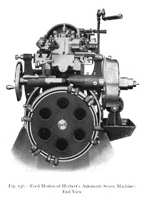
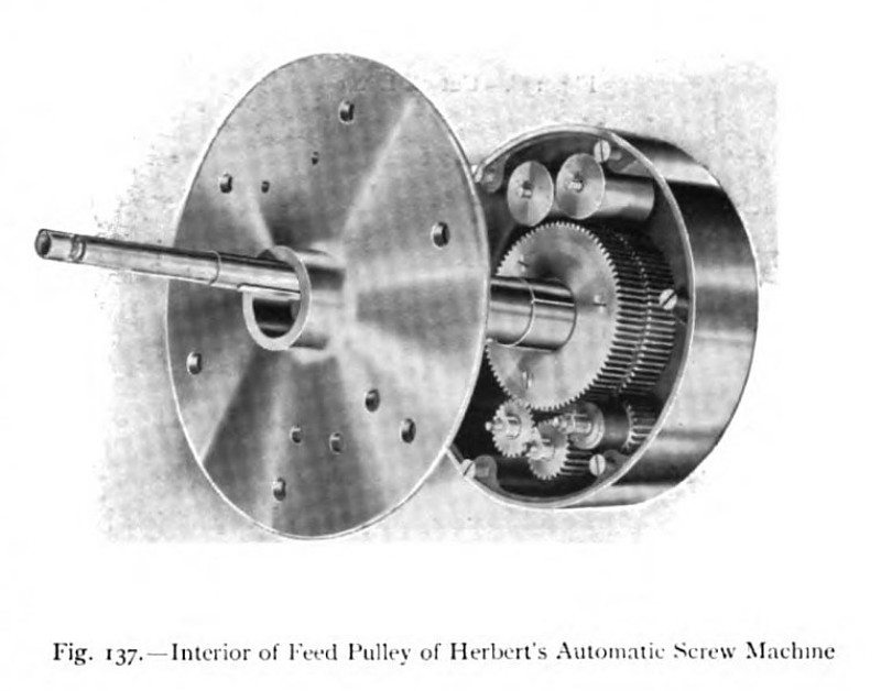
The capstan cam drum can also be set in several similar positions by sliding it along a keyway on the cam shaft, a locating pin being provided for fixing it. It is essential that the movable slide and the cam drum should be set in corresponding positions, to ensure the full action of the cam strips on the capstan-slide operating pin. As already stated, the feed motion which 'rotates the various cam drums is driven by a single feed belt at the right end of the machine but, by means of epicyclic gears contained within the feed pulley, two speeds are obtained. An end view of the machine, showing the feed motion and the driving pulley, is given in fig. 136, and the arrangement of the epicyclic gear wheels within the pulley is indicated in fig. 137. Wasted time can be reduced to a minimum by so adjusting the feed mechanism that all idle motions are performed at the quick speed. Thus, the tool may be made to move up to the work at the quick speed, then at the slow speed while the is being performed; and then, again, at the quick speed during the return motion and while the turret is being rotated. If certain of the tool positions are blank, the whole of the intermediate blank operations may be carried through on the quick speed. Any desired sequence of changes of speed, from fast to slow or slow to fast, can be obtained automatically by suitably adjusting the positions of the change- feed dogs, shown in fig. 131, upon the periphery of the change-feed disk. These dogs engage in rotation the change-feed lever and operate the two-speed gear in the feed pulley. In the intermediate position of the lever the feed motion is entirely disconnected, and in this position the lever can be held by lowering the feed plunger. If this plunger is lowered while the feed is working, the machine will automatically stop at the end of the operation. A handwheel on the feed worm shaft enables the machine to be wound by hand through the various operations. A third speed is obtained by changing the pinion on the intermediate stud, indicated in fig. 137, which shows the epicyclic gearing exposed for the purpose. This third speed is generally required only when a large speed ratio is desired; as, for example, when changing from operations on steel to those on brass. To avoid damaging any important part of the machine, in the event of the mechanism becoming jammed for any reason, the driving worm wheel is fixed to the cam shaft by means of a safety shearing pin of silver steel. This safety pin, which can be readily replaced, is sheared whenever the strain becomes unduly severe. |
|
 1911 Alfred Herbert, Ltd., #1 Automatic Screw Machine (Feed Motion)
 1911 Alfred Herbert, Ltd., #1 Automatic Screw Machine (Feed Pulley)
|
|