|
Title: |
1896 Image-Niles Tool Works, Special Pulley Lathe |
|
Source: |
Illustrations and Details of American Machine Tools-MIT 1896 pg 26 & Modern Mechanism 1895 pgs 463-464 |
|
Insert Date: |
10/19/2020 1:28:15 PM |
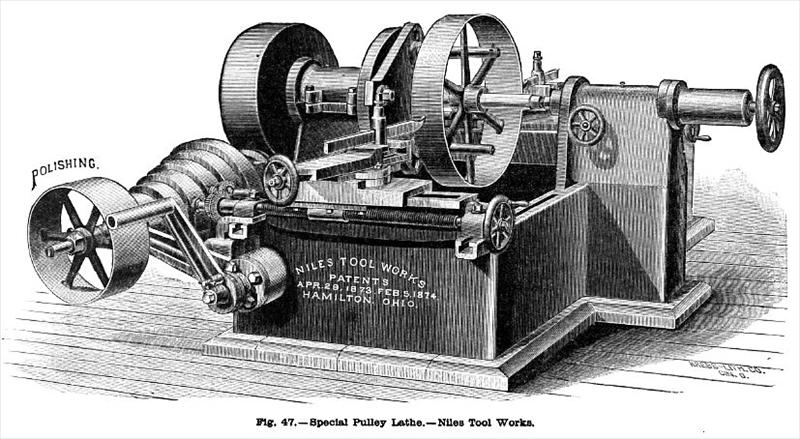
Pulley-Lathe—Fig. 47 shows a lathe built by the Niles Tool Works, of Hamilton, Ohio, especially designed for turning pulleys, gears (both spur, beveled, and mortised), small fly-wheels, and work of a similar character. Power is transmitted to the spindle through tangent gearing. The pulleys, being first bored, are placed on a mandrel and are driven by an equalizing driver, distributing the strain evenly on the arms. The tool-slides are mounted upon short, stiff cross-rails, which are adjustable on graduated surfaces of the bed to suit the diameter of pulley to be turned. The rails may be set over at an angle to give any desired degree of "crown." Tools are thus operated on both sides of the machines. Feeds are operated from the end of the driving-shaft by three-step cones for 1½-in. belt, communicating power to the feed-shaft by means of gears with an in-and-out pin. This arrangement gives a roughing and finishing feed for each adjustment of feed-belt. The front rest has compound movement and power cross and angle feed. The driving shaft runs at so much higher velocity than the main spindle that its speed is suitable for polishing while the lathe is turning.
US Patent: 138,394
http://www.datamp.org/patents/displayPatent.php?number=138394&typeCode=0 |
|
 1896 Niles Tool Works, Special Pulley Lathe
|
|