|
Title: |
1890 Article-Harrisburg Foundry & Machine Works, Ide Compound Steam Engine |
|
Source: |
The Steam User 1890 pgs 30-33 |
|
Insert Date: |
4/14/2011 8:06:17 PM |
These engines are being designed for nine expansions for rated capacities of engines. The first engine is provided with the automatic governor, and the second engine cuts off positively. The proportions are such that each engine will do an equal amount of work.
The cut-off in the low-pressure cylinder is also adjustable. This enables us to make proper adjustment to take care of the average load which an engine may be called upon to do. So that the initial pressure in the large cylinder will be equal to the final pressure of the small cylinder.
The cranks are placed at an angle of 90 degrees, which gives uniform motion. In addition to this, we have the benefit of our sensitive governor, to give additional advantages in the way of regulation; the aggregate power of the two engines will be produced without the great thrust on pistons, as would be the case of a high-pressure engine of the same capacity— in this way saving wear and tear on connections.
The connection between the two cylinders is made flexible, so that expansion will not disturb the alignment of the cylinders. The connection between the two engines is also very direct, and makes a receiver of sufficient capacity to allow of an initial pressure in the second cylinder about equal to the final pressure in the first.
In order to get the fullest possible advantage of the compound principle, we in neither case exhaust through the valve, but provide an outlet at each end of the valve for exhaust, and take steam in the centre, so that the heat of the live steam is not so readily conducted to the atmosphere by the exhaust, or, in case of condensing, to the condenser.
The connection between the two cylinders is thoroughly protected by non-conducting material and covered with jacket. It is allowed to be free at the one end, so that expansion and contraction will not be resisted by the jacket.
The two engines are placed upon a base-plate with a planed surface, and when engines are erected they are securely doweled and bolted to this base-plate. The base-plate is allowed to project a trifle on both ends of the engine. This base-plate can be put upon the foundation, and with the use of straight-edge can be brought properly into line; and on account of the projections on the end, it can at any time be examined and determined that it is not drawn out of line and placing the engines on a strain. This enables us to dismantle the engines, ship them separately, and have them erected without liability of getting them improperly set up.
The engines being double-acting, will make a large aggregate power at moderate speeds, without complication, and all the parts of easy access.
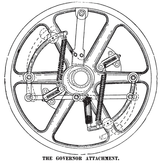
The governor represented in cut possesses some peculiar advantages not obtained in any of the numerous fly-wheel governors with shifting eccentrics. The shifting eccentric is not a new device, but the manner of adjusting the springs, in addition to the dash-pot, are special features in this governor, for which exclusive patents have been obtained covering these very vital features. When the governor is at rest it is obvious that the tension of the springs will hold the eccentric at a point giving the greatest possible throw. When in action the centrifugal force of the weights moves the eccentric across the shaft, reducing its throw by the centrifugal force as increased rotary motion takes place, holding the eccentric at a point where the tension of the springs and the centrifugal force of the weights are in exact equilibrium. If it were possible to obtain precisely uniform conditions in springs, the point of attachment for the spring might be demonstrated to a nicety, but as this is impossible, in order to obtain an absolutely uniform regulation of speed for the engine it is necessary to attach those springs to a point that will be in conformity with conditions that exist. In order to illustrate the advantage and necessity for a variable adjustment, we will assume that the springs were attached at a right angle to the curved links; it would then appear that, for every inch of movement of the lever at the point of attachment of spring, the same amount of extension would be required in the spring, which would offer great resistance to the centrifugal force, and in order to overcome this spring resistance, very heavy weights would be required. If, on the other hand, the attachment of the spring, in place of being at right angles to the curved levers, were attached at the fulcrum of these levers, there would be practically no extension of the spring, and consequently no resistance. We now have both extremes. In one case too much resistance, and in the other too little. There is, however, a mean which exactly equalizes the resistance of the spring and centrifugal force. This point cannot be obtained by any method of calculation, but is readily adjusted to meet each and every case as it exists; and when once adjusted will preserve this regulation until possibly long use of the spring may weaken its tension, when it is only necessary to adjust the nut on the end of the spring, and thereby secure the original tension, not changing its relative angle of adjustment to the lever. |
|
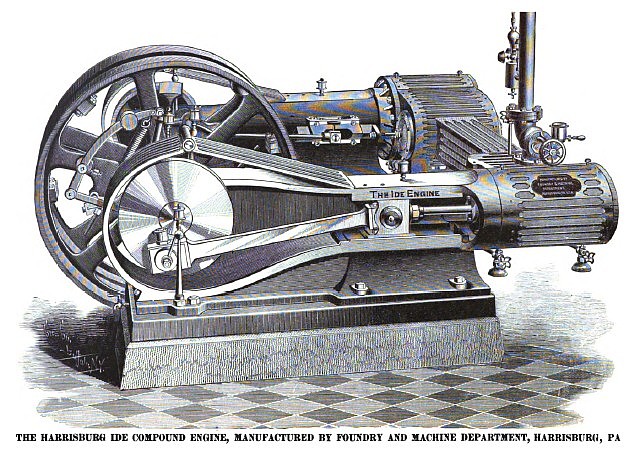 1890 Harrisburg Foundry & Machine Works, Ide Compound Steam Engine
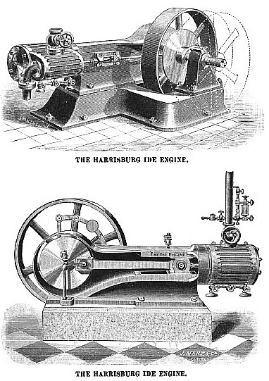 1890 Harrisburg Foundry & Machine Works, Ide Steam Engine
 1890 Harrisburg Foundry & Machine Works, Ide Steam Engine (Governor)
|
|