|
Title: |
1895 Article-Niles Tool Works, Horizontal Boring Machine |
|
Source: |
Modern Mechanism 1895 pg 76-77 |
|
Insert Date: |
6/7/2011 9:02:18 AM |
|
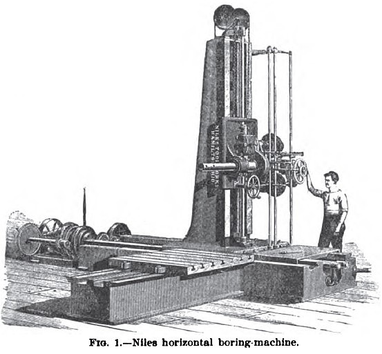
The Niles Horizontal Boring, Drilling, and Milling Machine is shown in Fig. 1. The machine consists of a heavy column 10 ft. 6 in. high, mounted on a bed-plate of any length to suit requirements. The column is 31 in. wide on the face, and is fitted with a heavy saddle, 40 in. square, carrying the spindle. The saddle has a vertical traverse on the column of 6 ft., and is raised and lowered by a heavy screw. It is balanced by a counter-weight hung in the column. The boring and milling spindle is of hammered steel 5½ in. in diameter. It slides in a heavy revolving sleeve, and has a traverse of 4 ft. It revolves in either direction, right or left hand, reversing by lever conveniently located, and has 8 power-feeds, ranging from to 1/20 in. to 1/4 in. per revolution of spindle. It is also provided with hand-feed and quick return. The milling-feeds are six in number, ranging from 1/12 to 9/16 in. per revolution of spindle. These feeds are applied only to the column and saddle, and are by power only. Any of these feeds for the quick motion may be utilized to set a drill, boring-bar or milling-cutter to work anywhere on the surface which the machine will reach. At one end of the bed-plate is placed the driving-gear, milling-feed, and quick-traversing mechanism for the column. The quick power traverse of the column has a speed of 5 ft. per minute. The driving-cone has six steps for a 4-in. belt, and is strongly back-geared, giving twelve changes of speed, ranging from 2 to 200 revolutions per minute, and has ample power for boring up to 24 in. diameter. A platen is placed in front of the column, convenient to the spindle, for the operator to stand on. |
|
 1895 Niles Tool Works, Horizontal Boring Machine
|
|