|
Title: |
1868 Article-Combination Molding and Planing Machine Co., Grosvenor's Molding Machine |
|
Source: |
Scientific American 09 Dec 1868 pg 369 |
|
Insert Date: |
5/4/2012 9:37:30 PM |
Improvement in Wood-Working Machinery
Before the invention of wood-molding machinery for curved work—which dates back only about fifteen years—the labor of producing moldings on curves by hand was very great, so great that this style of ornamentation was rarely used. The Woodworth planing machine and the ordinary wood-turning lathe are undoubtedly the originals from which the simple planing and molding machines for sash and door makers proceeded, and these, combined with the lathe for turning irregular forms, contain the principles of the variety molding machine. since the first inception of the machine, however, a number of important improvements have been made, being embraced in no less than nine patents.
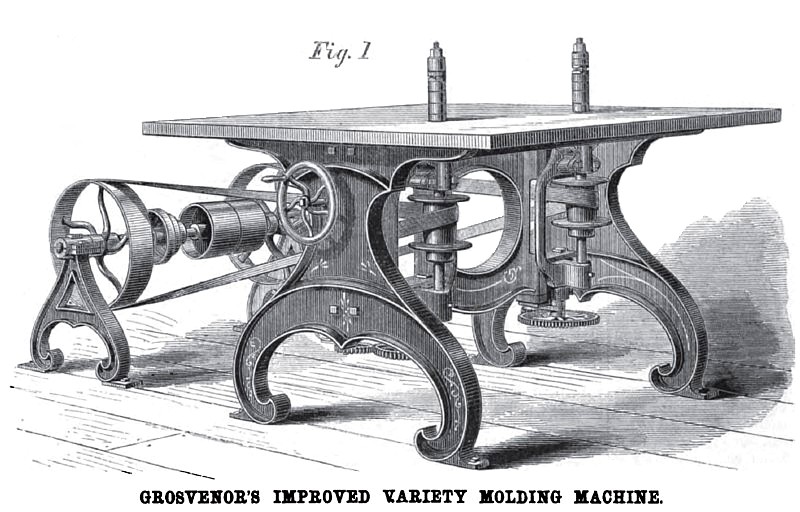
Fig. 1 is a perspective view of the machine for cutting moldings of any desired pattern, on curves, regular or irregular, and of any radii required. There are two upright cult r heads projecting above the top or table of the machine, driven by belts on flanged pulleys or drums, from a counter shaft, provided, as usual, with fast and loose pulley. Instead of raising or lowering the table to adjust the work to the cutters, as is generally done, the cutter heads and their shafts, boxes, and pulleys, with a frame in which all are held, are raised and lowered by means of a screw, gear, and a pinion on an up-right shaft, to each cutter head, so that one works independently of the other. The upright shaft, carrying the pinion at its lower end—that gives motion to the gear and screw directly under the cutter-head frame —has a bevel gear on its upper end connecting with a similar gear on a horizontal shaft under the table, provided -at its outer end with a hand wheel conveniently situated for the hand of the operator even when he is intently engaged in guiding the stuff to be cut.
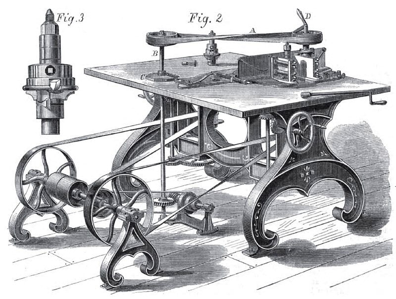
Fig. 2 is the same machine as Fig. 1 with the addition of a guide for cutting either straight or waved moldings. The guide is a plate which is held to the table top by two bolts for straight moldings. The guide is adjusted by means of horizontal screws at either end and held by set screws. The stock to be cut is fed between the guide and cutter-head by a roller on an upright shaft receiving motion by means of a belt, A, from a similar vertical shaft, B, that is driven by a belt from the counter shaft. This belt is taken from a cone on the counter to a similar cone to allow a change of feed. The shaft of the latter carries a worm that revolves the shaft, 15, and consequently the feed roller. Buffers or spring guides against which the stuff to be cut impinges in its passage, hold it well up to the vertical guide.
For waved molding the guide plate or platen on the table is pivoted at the forward end and held half a spiral or rubber spring, or by a weight at the other end to the ledge of a cam, C, on the shaft, B, which may be of any form desired to produce variations of the waved form. D is a shipper handle to stop or start the feed. This whole appurtenance is easily removed leaving the machine clear for irregular work as in Fig. 1, and may be as easily replaced in a moment.
Fig. 3 is an enlarged view of the cutter head used on both these machines. It is a combination of cutter head and rotary plane stock. Cylindrical flanges project downward from a disk or collar fitting the head stock and secured by set screws. These dished collars may be made of different sizes to suit the varying projections of the cutters from the head. In doing irregular work, where it is necessary to hold the stuff by hand to the cutter head, there has been danger of mutilating the hands by a sudden and undue action of the cutter upon the stuff in starting into the work. This has been a serious objection to other machines which this improved machine for irregular work has entirely obviated, it being impossible for an accident of this kind to occur. With this cutter head six or more cutters may be used at once to form a single molding; these may be out producing over thirty different forms with the same cutters, at a great saving of time and labor. The cutters may be set at such an angle that they may cut against the grain without splitting the wood.
The machine is well adapted for moldings, brackets, lattice work, etc., for house finishing. It is especially adapted to the furniture and cabinet maker; carriage builders, agricultural implement makers, pattern makers, car builders, boat makers, and workers in many other mechanical branches will find it a great assistance in the different departments of their business.
All letters and orders for machines should be addressed to the Combination Molding and Planing Machine Company, No. 424 East Twenty-third Street, New York.
Patent #s 16,144 & 20,345 |
|
 1868 Combination Molding and Planing Machine Co., Grosvenor's Molding Machine
 1868 Combination Molding and Planing Machine Co., Grosvenor's Molding Machine with Guide
|
|