|
Title: |
1872 Article-Rowley & Hermance Co., Phillip's Sash Coupling Machine |
|
Source: |
Scientific American, V 27 #8, 24 Aug 1872, pg. 118 |
|
Insert Date: |
3/5/2013 5:37:08 PM |
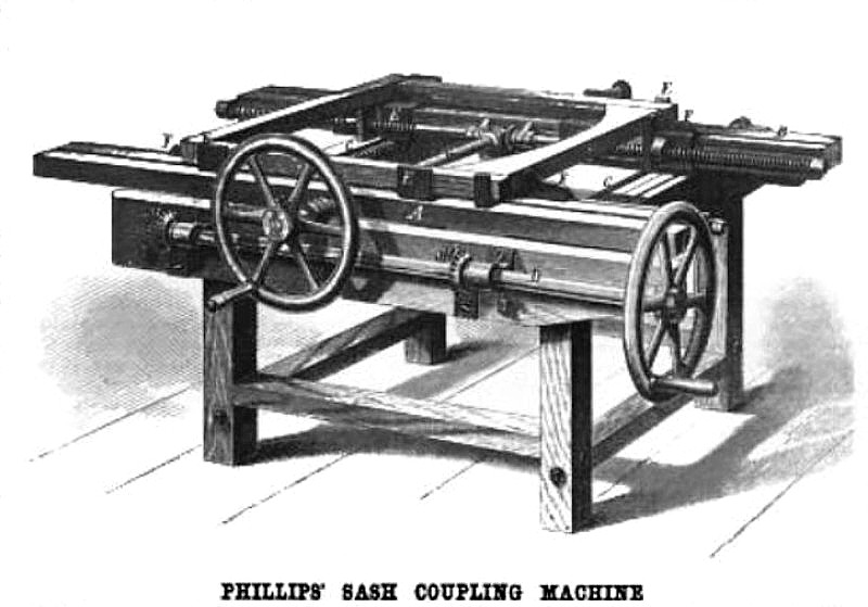
SASH COUPLING MACHINE
The improved sash clamp represented in our engraving is the invention of Mr. James H. Phillips, of Troy, N. Y., and was patented by him through the Scientific American Patent Agency, June18, 1872. Its construction we proceed to describe:
Upon a suitable frame, such for instance as depicted, are mounted two head blocks; one of which, A, is stationary, and the other, B, is movable toward or from the first, on the grooved ways shown on the top of the frame. These movements are produced by operating the two screws, C, which are geared to the hand crank shaft, D. The head blocks are provided with adjustable metal clamping pieces, E, upon which is laid, in the manner indicated in our illustration, the sash or other frame which it is intended to square up and press together. The peculiar form of these clamping pieces will be understood by inspecting those seen on B; they conform to the rectangular figure of the head block on three side, and on the fourth are turned up perpendicularly so as to clamp the frame perfectly square. By properly arranging the clamps, E, the terms of the side pieces of the sash frame are left room to project beyond the mortises in the end pieces through which they are driven, on being compressed by the machine.
The clamps by which the sides of the frame are held shown at F, are mounted on ways in the head blocks
and are operated by two pairs of twin right and left hand screws which are fitted to them. One of the pairs of screws runs in bearings attached to the head block, A. and the other in bearings connected with the movable block, B , the latter pair being so distinctly shown in the engraving that no further explanation is needed. Both pairs are geared to the crank shaft G, so as to he actuated simultaneously by its rotation, and the middle wheel of the gearing next B in arranged so as to slide with the block along the shaft, G.
When the clamps, E, are suitably adjusted, the machine is made to conform to any size and shape of frame, within its limits, by simply working the hand cranks, and the squaring and compressing of the frame is performed by it with ease and certainty
In order to allow the frames to he bored and pinned while yet clamped in the machine, the upper sides of the head blocks are made with longitudinal grooves, as represented, of sufficient depth and width to allow the boring tool to work clear through the frame to afford clearance for the chips and room clearance for the chips and room for the pin to project when driven. In securing the joints of doors, which is commonly done by splitting the tenons and driving in wedges, ample access is given to them between the clamps, E, and the wedges can be driven while the door is clamped.
The machine has received practical trial, and in claimed to be much superior to other hitherto used in sash finishing, saving both time and labor; a boy may operate it effectively.
The inventor, who wishes to dispose of a part or the whole of his rights, may be communicated with at 116 Congrell Street, Troy, N. Y.
Patent #128,064 |
|
 1872 Rowley & Hermance Co., Phillip's Sash Coupling Machine
|
|