|
Title: |
1912 Article-Blanchard Machine Co., Single Cylinder Oil Engine |
|
Source: |
Power Magazine, V36 #17, Oct 1912 pg. 608 |
|
Insert Date: |
4/4/2013 1:12:57 PM |
The Blanchard Oil Engine
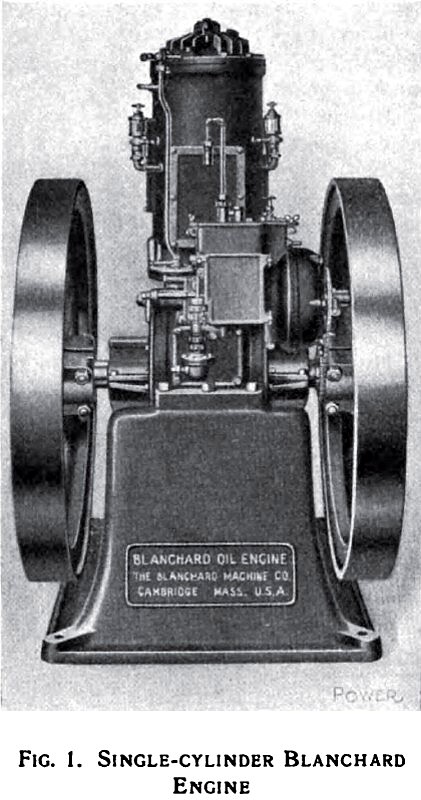
Among the latest additions to American oil-engine practice is the Blanchard engine built by the Blanchard Machine Co., of Cambridge, Mass., in sizes of from 8 to 100 hp. This is a slow-speed heavy-duty engine operating on the two stroke cycle with kerosene, distillate or fuel oils. Fig. 1 shows the general appearance of a single-cylinder Blanchard engine, although they are made with as many as four cylinders.
Only moderate compression is employed and as the oil is sprayed into the combustion chamber, is vaporized by the hot air and ignited by a hot tube, relatively slow combustion takes place; hence the engine is not subjected to such extreme pressure and shocks as prevails in the ordinary gas or gasoline engine.
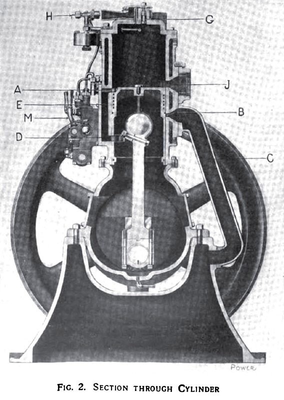
Considering the cycle of operation of the Blanchard engine, Fig. 2 represents a vertical section through the cylinder with the piston at the bottom of its stroke. As it starts on the upstroke it covers the inlet port A. The crank case is air-tight and as the air-intake port B is always covered except when the piston is at the top of the stroke, a partial vacuum is formed within the crank case. When the piston reaches the top of the stroke and uncovers the air-intake port, air is sucked into the crank case through the pipe C. On the down-stroke this air is compressed to about 5 lb. Just after the exhaust port F has been uncovered, the piston uncovers the transfer port D and the inlet port A, permitting the air confined in the crank case to rush through the passage E and, deflected by the piston, into the upper part of the cylinder. This serves to scavenge the cylinder. Upon the next up-stroke this fresh air is compressed to about 200 lb. (the exhaust and inlet ports being covered by the piston).
The heat of compression, together with that absorbed from the cylinder head, which is unjacketed, is sufficient to raise the temperature of the air to such a degree that the oil sprayed in is instantly gasified and is ignited by the hot plug G. In starting the engine this plug is first heated by the blow-torch H, but after the engine is in operation this is kept hot by the burning of each successive charge.
The injection of water into the combustion chamber forms a special feature of this engine.
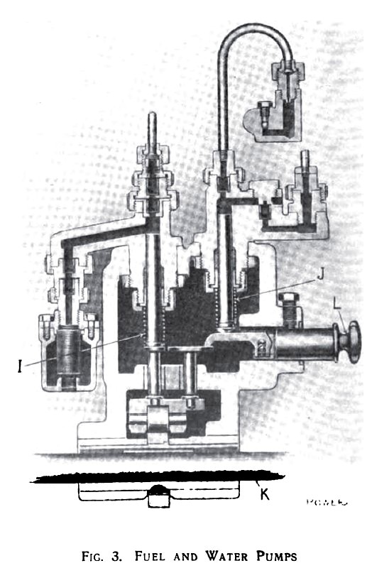
Fig. 3 is a section through the fuel feed mechanism, the oil pump on the left and the water pump on the right, I and J being the oil and water plungers respectively. Both are driven by the camshaft K. By pushing in or pulling out the piece L, which is held by a set-screw, the stroke of the water plunger is varied. In this way any desired proportion of oil and water can be had. This proportion then remains fixed, although the quantity of fuel admitted is determined by the governor, which regulates the length of stroke of the pump plungers. The lever M, Fig. 2, is for priming.
The governor is of special design and is guaranteed to regulate within 3 per cent, from no load to full load.
Article courtesy of Dennis Rouleau. |
|
 1912 Blanchard Machine Co., Single Cylinder Oil Engine
 1912 Blanchard Machine Co., Single Cylinder Oil Engine (Section Through Cylinder)
 1912 Blanchard Machine Co., Single Cylinder Oil Engine (Fuel & Water Pumps)
|
|