|
Title: |
1895 Article-J. & F. Howard, Portable Oil Engine |
|
Source: |
Engineering Magazine, V 59, 28 Jun 1895 pg. 828 |
|
Insert Date: |
11/5/2013 9:14:11 PM |
|
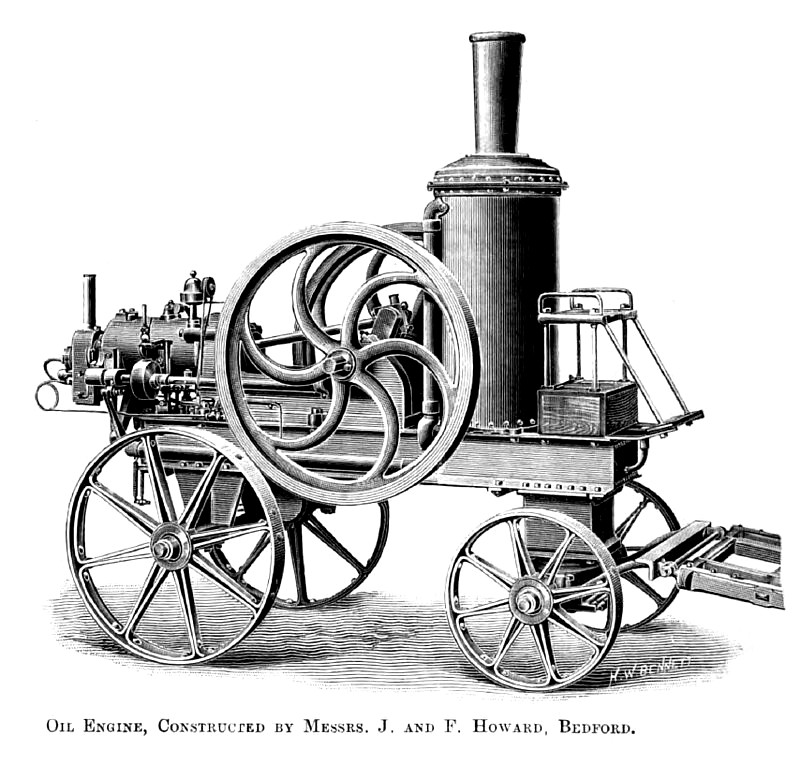
Messrs. J. and F. Howard were to have had an oil engine in the trials last year, but they were not able to get it ready in time. They show it now, both in the portable and fixed types. The former has a well-designed frame, capable of turning sharp corners, and of being set either end on to its work. Its general appearance is well shown in our view on page 828. A constantly burning lamp serves to keep both the igniting tube and the vaporizing tube hot. This lamp is fed from an air vessel, into which the oil is pressed by the pump. The same pump supplies the vaporizer, the surplus oil escaping under a loaded valve, and flowing back to the tank between the frames. The governor operates, through a hit-and-miss device, both an oil valve and an air valve; these two are opened simultaneously. The oil spurts, under pressure, into the vaporizer, where it is immediately met by a blast of air sucked through the vaporizer into the cylinder by the piston. The mixed charge is thus carried into the cylinder to be compressed on the backstroke of the piston. The casing at the base of the chimney is for cooling the water that circulates round the cylinder. The water is delivered by the pump to the top of the casing, and is distributed in spray by a kind of reaction wheel. It falls on to a number of strips of wood, placed on edge, and arranged in layers, each layer being at right angles to the layer below it. Air is drawn through these layers in the opposite direction by the action of the exhaust. The engine carries 30 gallons of water, and can work with this all day, only needing the addition of 2 or 3 gallons to make up for the evaporation. |
|
 1895 J. & F. Howard, Portable Oil Engine
|
|