|
Title: |
1914 Article-International Harvester Company of America, Tom Thumb Gas Engine |
|
Source: |
Gas Engines for the Farm, 1914, pg.s. 165-168 |
|
Insert Date: |
12/18/2013 7:18:25 PM |
I. H. C. Air-cooled Engines.
The International Harvester Company markets several complete lines of gas engines of various kinds. They are roughly divisible into water-cooled and air-cooled types.
The air-cooled engines are built in both vertical and horizontal types, the former in 2 and 3 horsepower sizes and the latter in units rated at 1, 2 and 3 horsepower respectively. The engine chosen for description is the 1 horsepower, horizontal engine marketed under the trade name of the Tom Thumb Famous Engine.
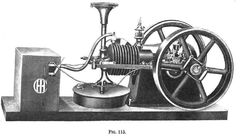
This engine is shown, mounted on a wooden base with all accessories, in Fig. 115. An idea of relative size can be obtained from the fact that the flywheel diameter is 15½ inches.
It will be observed that the cylinder is cast with radiating webs or fins and that a fan, shown behind the cylinder, forces air over these fins. The fan is driven by belt from the rim of the flywheel on the fan side of the engine.
The inlet valve, located in the cylinder head, is automatic. The air charge is drawn in through the right-hand branch of the forked pipe shown below the valve in the figure. The lower end of this branch is fitted with a throttling device for regulating the flow of air by hand.
The gasoline is contained in the circular galvanized-iron tank shown below the cylinder and is fed to the carburetor by suction. That is, the pressure around the fuel nozzle which is located in the left-hand branch of the inlet pipe is lowered during each suction stroke and atmospheric pressure on the surface of the fuel in the tank forces some of it up the fuel pipe and through the fuel nozzle. The quantity discharged through the nozzle is regulated by the needle valve located just above the fuel tank.
The exhaust valve is mechanically operated by a horizontal push rod running along the side of the cylinder as shown in the figure. This rod engages a horizontal lever running across the head of the cylinder, the lever being pivoted at its center to a stationary bracket. When the push rod moves its end of this lever to the left, as seen in the figure, the other end of the lever moves to the right and opens the exhaust valve against the pressure of its spring. The valve is closed by its spring when the returning lever and rod make this possible.
Governing is by hit and miss. The governor weights and springs are carried in the flywheel on the valve-gear side of the engine as shown in the figure. When these weights move out because of excessive speed, they operate a detent through bell cranks and a collar on the shaft. This detent fits into or behind, a projection on the push rod, which operates the exhaust valve, the projection being so located that the detent can engage it only when the exhaust valve is open. In this way the detent prevents the return of the push rod whenever the speed is above normal, thus holding the exhaust valve open and causing missed cycles until the speed decreases.
The burned gases are exhausted through the short vertical pipe shown above the exhaust valve. The muffler is located on top of this pipe and is of a type already described in a previous chapter.
Ignition is by high-tension jump spark, the spark plug being located on the top of the cylinder as shown in the figure. Batteries and coil are installed in the box shown at the left-hand end of the wooden base. The part of the primary circuit not within this box consists of the lightly insulated wires shown in the figure, the primary switch fastened to the side of the box, the metal of the push rod and engine and the timer or the contact maker shown on the upper side of the push rod near the cylinder head.
With the primary switch closed the timer makes and breaks the primary circuit by passing over the first fin on the cylinder as the push rod moves. This causes the passage of the necessary spark at the points of the spark plug, which forms part of the secondary circuit.
The part of the secondary circuit outside of the battery box consists of the heavily insulated wire leading to the plug, the insulated terminal and the metal of the plug, the metal of the engine and one of the primary wires.
This engine is a typical representative of the small, lightweight, air-cooled type which has been developed during the past few years to meet the demand for a small, readily portable engine for doing general work and odd jobs about the farm. Crated for shipping it weighs about 280 pounds, so that the weight of the outfit itself is a little less than this. Mounted on a two- or four-wheeled truck it is therefore readily portable and can easily be carried to the work instead of having to bring the work to the engine. |
|
 1914 International Harvester Company of America, Tom Thumb Gas Engine
|
|