|
Title: |
1908 Article-Reeves & Co., Double Cylinder Steam Traction Engine |
|
Source: |
The Traction Engine, Its Use and Abuse, 1908, pgs. 146-151 |
|
Insert Date: |
3/21/2014 11:40:46 AM |
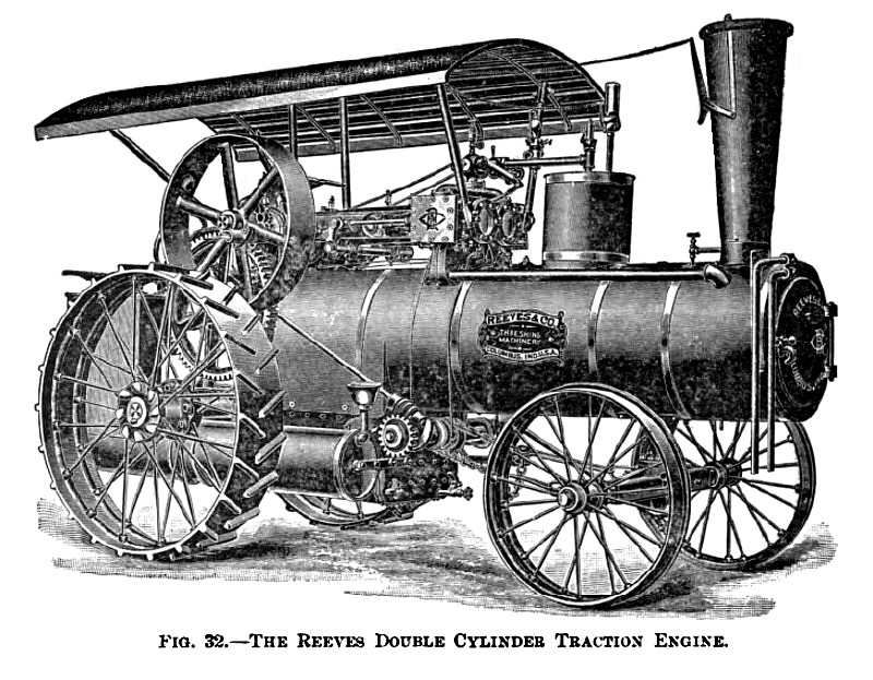
THE REEVES TRACTION ENGINE.
This engine, like the previous one, has all the machinery mounted on the boiler shell. The rear axle as well as the counter-shaft is supported on the rear of the boiler, and this results in a somewhat longer wheel-base than what is generally found in traction engines of this type.
The boiler is of the locomotive type of "water bottom" pattern; that is, the fire-box is surrounded by water on all sides. When engines have to be furnished for the use of straw or oil, as fuel, special arrangements of the fire-box are used. The most notable feature is the introduction in the fire-box of a fire-brick arch made in sections and provided with a socket-joint, which permits the expansion and contraction of the arch without injury. This arch protects the crown-sheet as well as the front end of the tubes from the direct flame.
This company's traction engines are generally furnished with special rocking grates very similar in construction to the rocking grates used in some of the larger house furnaces and just as easy to handle. The controller lever is operated from the engineer's platform. The smokestack is located in front, and immediately behind it is placed the steam dome. This is made somewhat higher than what is generally found to be the practice in order to insure dry steam.
Both an injector and an independent steam pump are furnished as well as an exhaust heater.
A cylindrical water-tank is placed alongside of the firebox and permanently piped both to injector and pump.
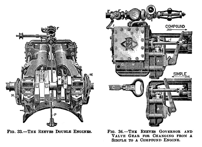
The engine is of the double-cylinder center-crank type with cranks at right angles. This results, as previously explained, in a machine with no dead centers. Each engine is complete and separate from the other, being only connected together by the crank-shaft. For each engine is provided an independent steam-chest, steam-valve, piston-head, cross-head, connecting-rod, etc. Only one governor of the horizontal type, one throttle-valve, and one steam-pipe is used for both engines. The steam-pipe branches to each engine below the throttle-valve. The cylinder, the frame, and the main bearing are all contained in one solid casting for each engine, and both engines are securely fastened to the same boiler saddle.
The crank-shaft is made of a steel forging in one piece and machined to size. The cross-head is provided with adjustable shoes. A reversing gear as well as an expansion controlling gear of special construction operated by a lever in the cab is used.
All fittings, such as sight-feed lubricator, steam gauge, water-glass, etc., are made of brass.
The main pulley is located on the crank-shaft and on the same side as the steering-wheel. The driving-wheels are connected by a train of spur-gears to the engine shaft. They are cast solid and provided with steel spokes cast into the hub and rims. The surface and the mud cleats have been chilled. The axle turns with the driving-wheels, and a compensating gear is introduced between it and the engine shaft.
If an engine of very high economy in regard to fuel is wanted, these engines are arranged to be cross-compounded. In this case a special valve-gear is furnished, which allows the engine to be used as a single engine with double cylinders but of larger power. When the cross-compound engine is used in the latter way, the economy is, of course, no greater than that of a single engine. Fig. 34 shows a cut of this valve gear. |
|
 1908 Reeves & Co., Double Cylinder Steam Traction Engine
 1908 Reeves & Co., Double Cylinder Steam Traction Engine (Details)
|
|