|
Title: |
1908 Article-C. Aultman & Co., Double Star Steam Traction Engine |
|
Source: |
The Traction Engine, Its Use and Abuse, 1908, pgs. 135-142 |
|
Insert Date: |
3/22/2014 7:57:14 PM |
THE AULTMAN CO.'S TRACTION ENGINE.
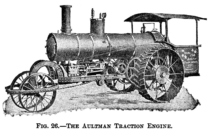
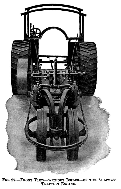
This engine has, like the previous one, the boiler and all the machinery supported on an independent steel frame built up of structural steel consisting mostly of I beams riveted together. As shown in the cuts, see Figs. 26 and 27, the engines have been placed directly on this frame in front of the fire-box and underneath the boiler. This construction not only relieves the boiler of all external strains, but also brings the center of gravity of the whole machine closer to the road; that is, makes it less top-heavy, which is a very good feature for any traction engine.
The front end of the frame is connected with the fifth wheel or "saddle" by means of arched girders or "goose necks," allowing the front wheels to turn completely around if wanted and also giving to the whole frame a certain amount of elasticity which is very desirable.
In order to reduce the work of steering the front axle "saddle" has been furnished with ball bearings.
The placing of the front wheels ahead of the boiler has necessarily produced a somewhat longer wheel base than if the boiler itself had been used for the support of the front axle, but the great angle through which the front wheels can be turned more than balances this disadvantage.
The boiler is of the locomotive type with the smokestack in front when coal or wood is to be used for fuel. The return tubular type with the smokestack in the rear is furnished when the fuel is to be straw. The fire-box is completely surrounded by water, and has the fire and the ash door set in a removable cast-iron frame. Practically the same fittings are furnished as in the case of the Eclipse Traction Engine.
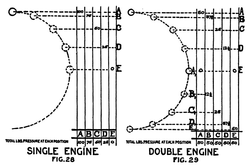
Two independent engines with cranks at quarters and four bearings are used. I will say here that the advantage of using two engines with cranks at quarters on a traction engine over the single crank engine is quite marked. The locomotive engineers have a long time ago recognized this, and today nearly every locomotive is therefore furnished with two engines. To illustrate this the following two diagrams have been prepared. Referring to Fig. 28, which represents a diagram of a single crank engine during a quarter of a revolution of its fly-wheel, the letters A, B, C, D, and E represent positions of the crank. The figures placed opposite those letters represent the pressure of the crank-rod on the main shaft in these various positions. Supposing that the amount of pressure exerted in the position A is 100 as per diagram, then the pressure is zero when the crank is in position E or passing through the dead center. At the position B the pressure is then 75, at C 50, etc. Suppose, now, that instead of the single crank engine we substitute two engines with cranks at quarters having together the same amount of power as the previous single engine. Referring to Fig. 29, representing a diagram of two single crank engines with cranks at quarters during a quarter of a revolution, and allowing the letters A and A', B and B', etc., to represent the positions of the cranks at the same instant, then the figures set opposite those letters will also represent the pressures on the main shaft in those various positions at that instant.
As we supposed above that the total amount of power to be furnished by these two engines should be equal to the amount of power furnished by the single engine, it follows that each individual engine needs only to furnish one-half the power. By looking at the diagram Ave find, therefore, that the power exerted in the position A is in this case only 50, at B 37½, at D 12½, and at E zero for the one engine. The figures for the other engine at the same positions commencing with A' (where it is zero) is at B' 12½, at D' 37½, and at E' 50. As the two cranks are connected together, the total amount of pressure on the main shaft is, therefore, represented by adding together the amount of pressure, which each engine exerts in corresponding positions. Doing this we find, as the diagram shows, that the total amount of pressure will be 50 in all those positions. If we now go back to the first diagram representing the single crank engine, we find that in the position A the power exerted was 100, whereas in this case we have only 50 for the double engine. At the position B the single crank engine exerts a pressure of 75, whereas the double crank engine only shows 50. At the position C both engines show the same amount of pressure, or 50. At position D the single crank engine has dropped to 25, but the double crank engine still remains 50. At position E the single crank engine exerts zero power, whereas the double crank engine still shows 50. A careful study of the above shows that, though the total amount of power developed by these two classes of engines is nearly the same, the distribution of this power during the quarter of a revolution is very materially different. The double engine exerts nearly a uniform amount of power during this period, whereas in the single engine the power varies from a maximum of nearly twice the amount of the double engine to a minimum of zero. This lack of uniformity as well as the absolute dead center have to be taken care of in the single crank engine by the fly-wheel. The double crank engine can, therefore, theoretically do without the fly-wheel. From the above we can see why the double engine with cranks at quarters is preferable for traction purposes.
The crank-shaft in this engine is of the built-up type, allowing the use of large bearings. The valves are balanced and the standard "locomotive link" reversing gear is used.
Due to the position of the engines, all their parts are well protected, easy to inspect, oil, and clean.
The height of the driving pulley on the engine shaft is convenient for handling the main belt directly from the ground without climbing, and its position is such that there is no interference between the belt and any part of the traction engine.
The power is transmitted from the engine shaft to the traction wheels in a straight line through a train of spur gears, and the engine is provided with a set of double speed gears. The differential or compensating gear is placed inside the traction wheel. The manufacturer of this engine uses cast-steel fore gears and pinions. The traction wheels are of the built-up type with rolled steel rims and forged steel spokes and the mud cleats are of malleable cast-iron riveted to the rims. |
|
 1908 C. Aultman & Co., Double Star Steam Traction Engine
 1908 C. Aultman & Co., Double Star Steam Traction Engine (Details)
 1908 C. Aultman & Co., Double Star Steam Traction Engine (Table)
|
|