|
Title: |
1878 Article-Hayward, Tyler, & Co., Rider's Patent, Hot Air Engine |
|
Source: |
International Exhibition at Paris, 1878, pg. 115 |
|
Insert Date: |
1/27/2015 3:51:27 PM |
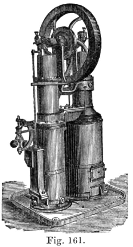
The " Rider " Hot Air Engine consists essentially of a compression cylinder and a power cylinder, with their respective pistons and connections, and a regenerator.
The lower portion of the compression cylinder is kept cold by a current of water which circulates through the cooler, which surrounds the lower portion of the cylinder, while the lower portion of the power cylinder is kept hot by the action of the fire below the heater.
The heating, and also the cooling of the air, is instantaneously effected by its alternate presentation to the surfaces of the heater and cooler, in a thin annular sheet, such being found by experience to be the only correct method of rapidly and thoroughly effecting changes of temperature in air.
This is accomplished as follows :—The compression piston extends downwards to the base of the engine, and is a trifle smaller than the interior of the cooler, thus leaving a thin space on all sides for the air to pass downward and become thoroughly cool on its way to the bottom, and through which space it flows on its way back to the heater.
The power piston likewise extends downwards into the heater, which in shape resembles the bottom of a champagne bottle, that is, rising in the centre, and presenting to the action of the fire a narrow annulus all around the bottom. Within this heater is the telescope, which is a thin iron cylinder, about one-fourth of an inch less in diameter than the interior of the heater. It is fitted to the interior of the power cylinder and extends nearly to the bottom of the heater. Its office is to cause the air which flows from the compression cylinder to be presented in a thin sheet all around the interior surface of the heater, and particularly at the lower and hotter portion. By this means the air is thoroughly and rapidly heated.
The same air is used continuously, as there is neither influx nor escape, the air being merely shifted from one cylinder to another.
Between the compression and power cylinders is situated the regenerator, the economical value of which cannot be overrated. This regenerator is composed of a number of thin plates slightly thickened at their edges, which, while affording a free passage to the air, subdivides it into thin sheets. It is so placed between the cylinders as to be traversed by the air in its passage each way between the hot and cold cylinders. Thus the heat is alternately abstracted from and returned to the air in its passage backwards and forwards through these plates, imparting great economy and steadiness of power to the engine.
The two pistons are attached directly to the cranks (which stand at an angle of about 95 degrees with each other, the crank of the power piston being in advance), by simple connecting rods, and all the movements of the various
parts are uniform, being solely derived from regular, circular, and rectilinear motion; and as there are no complicated parts, and none of the irregular intermittent impulses which characterize caloric engines, a high rate of speed and smooth action may be safely and easily obtained.
The leather packings are in duplicate for each plunger. The lower one has its lap downwards to resist the escape of air below the piston, while the upper one has its lap upwards to prevent the lubricating material from entering too freely into the cylinders.
Between them is the relief ring, which is so constructed as to almost entirely relieve the friction of the packings.
A check valve is fitted which supplies any slight leakage of air, which may occur. It ia generally placed at the back of the engine, at the lower part of the compression cylinder, for supplying any slight leakage of air which may occur.
When the engine is in perfect working order the check or "suck in" valve will only work for a few revolutions on starting the engine. Should the engine be found to draw in air continuously through this valve it is a sure indication of leakage somewhere, which should be stopped, otherwise a great loss of power will result.
The mode of working the engine is briefly a a follows:—The compression piston first compresses the cold air in the lower part of the compression cylinder into about one-third its normal volume, when, by the advancing or upward motion of the power piston, and the completion of the down-stroke of the compression piston, the air is transferred from the compression cylinder, through the regenerator, and into the heater without appreciable change of volume. The result is a greater increase of pressure, corresponding to the increase of temperature, and this impels the power piston up to the end of its stroke. The pressure still remaining in the power cylinder and re-acting on the compression piston forces the latter upward till it reaches nearly to the top of its stroke, when, by the cooling of the charge of air, the pressure falls to its minimum, the power piston descends, and the compression again begins. In the meantime the heated air, in passing through the regenerator, has left the greater portion of its heat in the regenerator plates, to be picked up and utilized on the return of the air towards the heater. This process recurs at each revolution.
The heater is made of a peculiar mixture of iron with the view of durability, but as cast iron is liable to become deteriorated if subjected to an intense heat care should be taken to prevent the possibility of such an occurrence.
The packings are simple discs of leather, and will last a very long time without renewal; those on the hot cylinder are kept cool by a small stream of water, which circulates round the upper portion of the cylinder, so that there is no danger of over-heating them.
The connecting rods are of the best known construction. Their ends are made of gunmetal, connected together by a tube, in which is fitted a rod, extending from the upper to the lower brass, and so arranged that one key, capable of nice adjustment by nuts, at once compensates for the wear on both upper and lower brasses. This tube also permits the oil to flow down to the lower brass, and thus both ends are lubricated from the oil cup at the same time. It will be seen that this construction is at once efficient and durable; no loose straps, gibs, or other pieces are used, and there is no chance of consequent breakage. |
|
 1878 Hayward, Tyler, & Co., Rider's Patent, Hot Air Engine
|
|